. 2021 May 17;12(1):2895.
doi: 10.1038/s41467-021-23000-7.

Demonstration of a compact plasma accelerator powered by laser-accelerated electron beams

Affiliations

Demonstration of a compact plasma accelerator powered by laser-accelerated electron beams

T Kurz et al. Nat Commun. .

Abstract

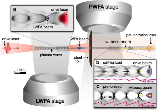
Plasma wakefield accelerators are capable of sustaining gigavolt-per-centimeter accelerating fields, surpassing the electric breakdown threshold in state-of-the-art accelerator modules by 3-4 orders of magnitude. Beam-driven wakefields offer particularly attractive conditions for the generation and acceleration of high-quality beams. However, this scheme relies on kilometer-scale accelerators. Here, we report on the demonstration of a millimeter-scale plasma accelerator powered by laser-accelerated electron beams. We showcase the acceleration of electron beams to 128 MeV, consistent with simulations exhibiting accelerating gradients exceeding 100 GV m-1. This miniaturized accelerator is further explored by employing a controlled pair of drive and witness electron bunches, where a fraction of the driver energy is transferred to the accelerated witness through the plasma. Such a hybrid approach allows fundamental studies of beam-driven plasma accelerator concepts at widely accessible high-power laser facilities. It is anticipated to provide compact sources of energetic high-brightness electron beams for quality-demanding applications such as free-electron lasers.


Conflict of interest statement

The authors declare no competing interests.

Figures

Fig. 1
Fig. 1. Schematic overview of the experiment.
Two consecutive gas jets form the basis of an LWFA-driven PWFA. A high-intensity laser pulse (red) drives an LWFA in the first stage, generating a high peak-current electron beam (blue). The spent LWFA laser is reflected by a thin steel foil, whereas the electron beam propagates into the second stage, acting as the PWFA driver. In the PWFA stage, a witness beam (yellow) is accelerated. In addition, a counter-propagating low-power laser pulse can be applied for generating a pre-formed plasma channel in the PWFA stage prior to the drive beam arrival. a Illustration of a plasma wave driven by the high-intensity laser, with electron density in gray. b Plasma wave generated by the LWFA electron beam in the self-ionized PWFA regime. c Excited plasma wave in the pre-ionized PWFA regime. Images shown in a, b, c are obtained from simulations using the code OSIRIS. The purple line in b and c represents the longitudinal electric field on axis, considering only the interaction of the drive beam with the second gas jet.
Fig. 2
Fig. 2. Representative electron spectra, plasma wave shadowgrams, and statistical analysis of witness beam energy.
a Energy spectrum of LWFA electrons transmitted through the steel foil without operating the PWFA stage, with θ representing the divergence. b LPWFA spectrum without pre-ionizing laser. c LPWFA spectrum with the PWFA stage ionized prior to the drive beam arrival. d Charge distribution integrated over ±6 mrad divergence: green line corresponds to a, orange to b, and blue to c. Additional spectra used for determining the statistical parameters can be found in Supplementary Fig. 3, with the measured drive beam parameters from all shots summarized in Supplementary Table 1. e Plasma wakefield shadowgram at the center of the PWFA stage, with the drive beam propagating to the right and ionizing the gas by means of its electric field (self-ionized case). The ionized channel (dark region) and several plasma wakefield oscillations directly behind the driver are visible. f Corresponding shadowgram of a plasma wakefield in the pre-ionized case. The plasma wave structure is more pronounced and shows more subsequent cavities than in the self-ionized case, indicating a stronger wakefield excitation. g Measured witness energy correlated with the remaining spectral charge density of the drive beam. The data points represent spectra exhibiting clear witness beams in the pre-ionized (orange, 37% of shots) and self-ionized case (blue, 28% of shots). The squares denote the mean value of each set with error bars visualizing the root mean square shot-to-shot fluctuations and ellipses encircling the area of 2 SDs. Operating the LPWFA with pre-ionization results in consistently higher witness beam energy gain together with stronger driver degradation.
Fig. 3
Fig. 3. Start-to-end simulation for the pre-ionized case.
a Plasma density profile in the simulation, according to the actual experimental geometry and measured density profiles for both gas jets. The drive laser pulse propagates to the right. b Electron density distribution in the PWFA stage, 0.8 mm after the foil. The LWFA electron beam excites a plasma wakefield, with the witness beam accelerating at the back of the first cavity. ζ = z − ct represents the co-moving coordinate parallel to the drive beam propagation direction z, with c and t denoting the speed of light and time, respectively. The red line is the on-axis longitudinal electric field and the shaded areas on the bottom show the current profiles of the driver (blue) and witness beam (orange). c Simulated electron spectrum after the LWFA stage (z = 3.3 mm), showing a similar peaked energy distribution of the drive beam (blue) as measured in the experiment. d Just before the foil (z = 3.9 mm), the wakefield driven by the spent laser pulse leads to an energy gain of the LWFA electrons. e After the PWFA stage (z = 6.5 mm), a strong degradation of the driver along with energy gain of the witness beam (orange) is observed.
Fig. 4
Fig. 4. LPWFA using a drive-witness bunch pair.
a Averaged electron spectra with 95% confidence intervals for LWFA-only reference shots (200 consecutive shots, blue solid line) and with the second stage operated at lower plasma density than the LWFA stage, at 1.4 × 1018 cm−3 (200 consecutive shots, orange solid line) and 2.1 × 1018 cm−3 (200 consecutive shots, gray line), respectively. Blue and orange dashed lines correspond to a representative single shot from the associated data set in which a clear distinction of the driver and the witness electron spectrum is even more pronounced. For the higher density PWFA case, a representative single shot cannot be shown due to the onset of spectral overlap between the drive and witness beam, and large shot-to-shot fluctuations. The detection range of the spectrometer starts at 25 MeV. b Simulated electron density in the LWFA stage, illustrating that two bunches are injected into the first and second wakefield cavity, subsequently acting as a driver-witness pair in the PWFA stage. ζ represents the co-moving coordinate parallel to the laser propagation direction z. c, d Simulation snapshots in the PWFA stage, corresponding to the lower and higher plasma density setting in the experiment, respectively. The red lines correspond to the longitudinal on-axis electric field, showing that the plasma wave is driven by the electron bunch originating from the first LWFA cavity, whereas the contribution of the laser remnant to the wakefield formation is negligible. The accelerating phase witnessed by the electron bunch from the second LWFA cavity is controlled by tuning the plasma density. Further information regarding the pair bunch parameters and simulation details can be found in Supplementary Note 4.

References

    1. Chen P, Dawson JM, Huff RW, Katsouleas T. Acceleration of electrons by the interaction of a bunched electron beam with a plasma. Phys. Rev. Lett. 1985;54:693–696. doi: 10.1103/PhysRevLett.54.693. - DOI - PubMed
    1. Rosenzweig JB, Breizman B, Katsouleas TC, Su JJ. Acceleration and focusing of electrons in two-dimensional nonlinear plasma wake fields. Phys. Rev. A. 1991;44:R6189. doi: 10.1103/PhysRevA.44.R6189. - DOI - PubMed
    1. Lotov KV. Blowout regimes of plasma wakefield acceleration. Phys. Rev. E. 2004;69:46405. doi: 10.1103/PhysRevE.69.046405. - DOI - PubMed
    1. Tzoufras M, et al. Beam loading in the nonlinear regime of plasma-based acceleration. Phys. Rev. Lett. 2008;101:145002. doi: 10.1103/PhysRevLett.101.145002. - DOI - PubMed
    1. Tajima T, Dawson JM. Laser electron accelerator. Phys. Rev. Lett. 1979;43:267–270. doi: 10.1103/PhysRevLett.43.267. - DOI