. 2021 Apr 1;10(4):25.
doi: 10.1167/tvst.10.4.25.

Computational Model-Based Estimation of Mouse Eyeball Structure From Two-Dimensional Flatmount Microscopy Images

Affiliations

Computational Model-Based Estimation of Mouse Eyeball Structure From Two-Dimensional Flatmount Microscopy Images

Hongxiao Li et al. Transl Vis Sci Technol. .

Abstract

Purpose: Retinal pigment epithelial (RPE) cells serve as a supporter for the metabolism and visual function of photoreceptors and a barrier for photoreceptor protection. Morphology dynamics, spatial organization, distribution density, and growth patterns of RPE cells are important for further research on these RPE main functions. To enable such investigations within the authentic eyeball structure, a new method for estimating the three-dimensional (3D) eyeball sphere from two-dimensional tissue flatmount microscopy images was investigated.

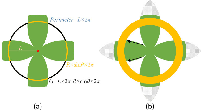
Methods: An error-correction term was formulated to compensate for the reconstruction error as a result of tissue distortions. The effect of the tissue-distortion error was evaluated by excluding partial data points from the low- and high-latitude zones. The error-correction parameter was learned automatically using a set of samples with the ground truth eyeball diameters measured with noncontact light-emitting diode micrometry at submicron accuracy and precision.

Results: The analysis showed that the error-correction term in the reconstruction model is a valid method for modeling tissue distortions in the tissue flatmount preparation steps. With the error-correction model, the average relative error of the estimated eyeball diameter was reduced from 14% to 5%, and the absolute error was reduced from 0.22 to 0.03 mm.

Conclusions: A new method for enabling RPE morphometry analysis with respect to locations on an eyeball sphere was created, an important step in increasing RPE research and eye disease diagnosis.

Translational relevance: This method enables one to derive RPE cell information from the 3D eyeball surface and helps characterize eyeball volume growth patterns under diseased conditions.


Conflict of interest statement

Disclosure: H. Li, None; H. Yu, None; Y.-K. Kim, None; F. Wang, None; G. Teodoro, None; Y. Jiang, None; J.M. Nickerson, None; J. Kong, None

Figures

Figure 1.
Figure 1.
Schema of 2D flatmount images from 3D eyeballs after cutting and unfolding. Ideal flatmount images of a sphere cut into (a) 100 and (b) 500 meridians unfolded from the north pole with the tip on the south pole fixed, respectively, are shown.
Figure 2.
Figure 2.
A schema of a 3D eyeball spherical model where O, N, and S are the center, north, and south poles of the sphere, respectively, are shown. Point A is an arbitrary point on the sphere surface. The resulting lines ON and OA form the angle θ. Point C and D are on the line OA and ON and equally distant from the origin O. South pole S of this spherical model corresponds to the optic nerve head; the top dome of the sphere represents the cornea. The length of line OA is the sphere radius R, whereas the length of the arc from A to S on the sphere is denoted as L = R × (π − θ) in black. Additionally, the circle perimeter of the top dome is R × sin θ ×  2π in blue; the length of the arc from the north pole N to the south pole S is π × R in green.
Figure 3.
Figure 3.
Schema of flatmount tissues on the south pole plane. (a) A schema in which the sphere is evenly cut into four lobes and pushed down to the south pole plane is shown. As an example of the concentric circles, the overlaid circle has radius L and perimeter L ×  2π. The yellow arcs represent the dome circle in Figure 2, with a length sum R × sin θ ×  2π. Black arcs indicate gaps between the neighboring lobes, and the resulting arc length sum is G = L ×  2π − R × sin θ ×  2π. (b) Solid arrows indicate the directions of the tissue distortions in the flattened lobe. The yellow ring indicates the equatorial zone of the sphere. The gray crosshatched areas represent the cornea components in the eyeball.
Figure 4.
Figure 4.
A plot illustrating the change between the sphere latitude perimeter and the concentric circle perimeter. Given R is the sphere radius, the sphere latitude perimeter (red), the concentric circle perimeter (green), and their difference (i.e., the gap length in blue) as a function of concentric circle radius L are plotted. The sphere latitude perimeter reflects tissue cohesion, whereas the concentric circle perimeter suggests the effect of the flattening force.
Figure 5.
Figure 5.
Flatmount microscopy image analysis and measurement. (a) A typical flatmount microscopy image is shown. The orange component at the tip of each lobe corresponds to the cornea in the northern hemisphere. (b) A processed image is shown. The flatmount image is transformed into the hue, saturation, value (HSV) color space, and Otsu's threshold is applied to the saturation channel for differentiation of the background regions in yellow and the foreground tissue regions. An example concentric circle is illustrated in red. The number of pixels on the red circle over the background region in yellow is counted to measure the length of the gap between lobes G. A red point on the optic nerve head is annotated at the origin of the concentric circles. The four blue points (i.e., lobe-marker points) are used to determine the middle axis lengths of four lobes: M1, M2, M3, and M4.
Figure 6.
Figure 6.
Estimates of the tissue distortion coefficient k based on full and partial data points. The estimates of tissue distortion coefficient k are plotted from 23 samples based on the full dataset and partial data points excluding 10%, 20%, and 30% of data points from (a) the low-latitude zones and (b) the high-latitude zones. Differences in tissue distortion coefficient estimate k between the full data point set and the partial dataset with partial data point removal from the (c) low-latitude and (d) high-latitude zones. A typical tissue flatmount image is shown with its fitting curves associated with tissue distortion coefficient k estimated with the full dataset and partial data points not including some from the (e) low-latitude and (f) high-latitude zones. These fitting curves are associated with tissue distortion coefficient k estimated with distinct data point sets: (blue solid) theoretic tissue interlobe gaps from Equation (1) with the ground truth radius; (red solid) full dataset; (green dashed) partial data points with 10% of data points excluded; (blue dash-dotted) partial data points with 20% of data points excluded; (purple dotted) partial data points with 30% of data points excluded.
Figure 7.
Figure 7.
Estimates of eyeball radius with distinct tissue distortion coefficient strategies. The eyeball radius estimates from distinct learning methods are shown for the tissue distortion coefficient and compared with the eyeball ground truth: three-fold CV, five-fold CV, LOO-CV, and the all-sample strategy (i.e., the tissue distortion coefficient learned from 23 testing samples applied to the same 23 testing samples).
Figure 8.
Figure 8.
Radius comparison with the ground truth, the radius estimated with the tissue distortion coefficient using the LOO-CV strategy, and the estimate from the model without the tissue deformation correction term.
Figure 9.
Figure 9.
Representative tissue flatmount microscopy image examples from three classes are illustrated with the relative error: (left column) ≤5%, (middle) 5%–10%, and (right) >10%. Two flatmount microscopy image samples from each class are shown. The sample number and the relative error are above each sample image.
Figure 10.
Figure 10.
Representative samples with relatively large (top), medium (middle), and small (bottom) differences between measured and fitting interlobe gap curves. Flatmount tissue images of samples 4, 1, and 16 are on the left. Their interlobe gap curve fitting plots are on the right. The blue curve represents the measured gaps derived from flatmount imaging data; the red curve is the fitting curve derived from Equation (3).

Similar articles

References

    1. Boyer MM, Poulsen GL, Nork TM. Relative contributions of the neurosensory retina and retinal pigment epithelium to macular hypofluorescence. Arch Ophthalmol. 2000; 118: 27–31. - PubMed
    1. Strauss O. The retinal pigment epithelium in visual function. Physiol Rev. 2005; 85: 845–881. - PubMed
    1. Liang FQ, Godley BF. Oxidative stress-induced mitochondrial DNA damage in human retinal pigment epithelial cells: a possible mechanism for RPE aging and age-related macular degeneration. Exp Eye Res. 2003; 76: 397–403. - PubMed
    1. Ach T, Huisingh C, McGwin G Jr., et al. .. Quantitative autofluorescence and cell density maps of the human retinal pigment epithelium. Invest Ophthalmol Vis Sci. 2014; 55(8): 4832–4841. - PMC - PubMed
    1. Hanus J, Anderson C, Sarraf D, Ma J, Wang S. Retinal pigment epithelial cell necroptosis in response to sodium iodate. Cell Death Discov. 2016; 2: 16054. - PMC - PubMed

Publication types