. 2021 Jun 17;18(4):10.1088/1741-2552/ac02dc.
doi: 10.1088/1741-2552/ac02dc.

Flexible, high-resolution thin-film electrodes for human and animal neural research

Affiliations

Flexible, high-resolution thin-film electrodes for human and animal neural research

Chia-Han Chiang et al. J Neural Eng. .

Abstract

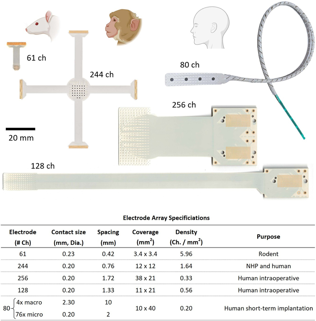
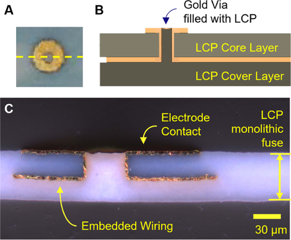
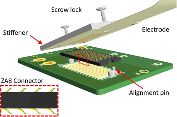
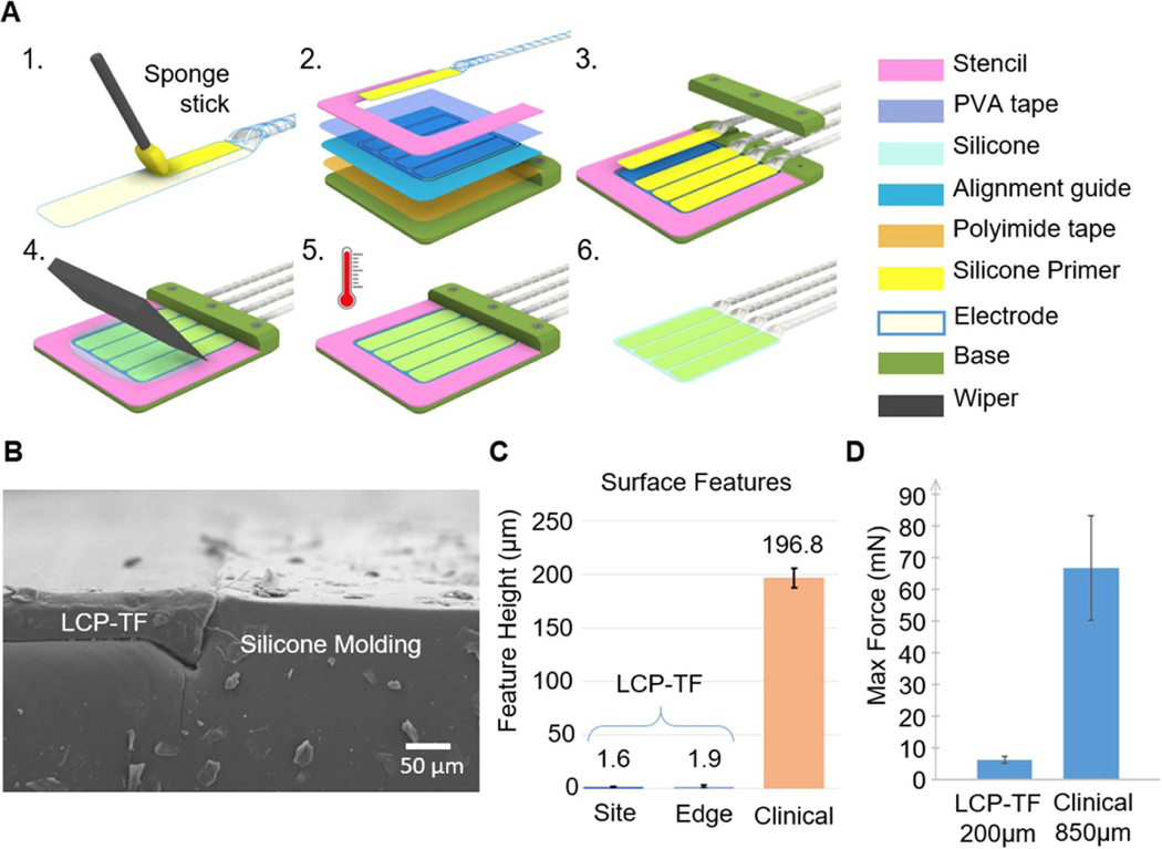
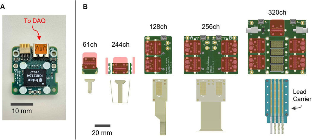
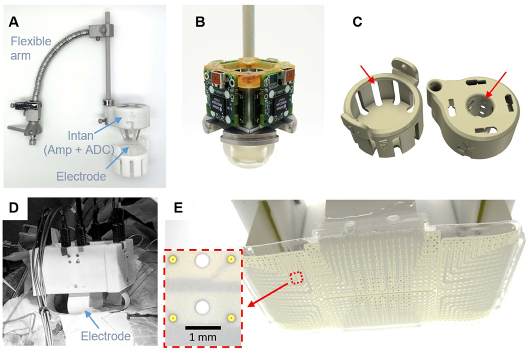
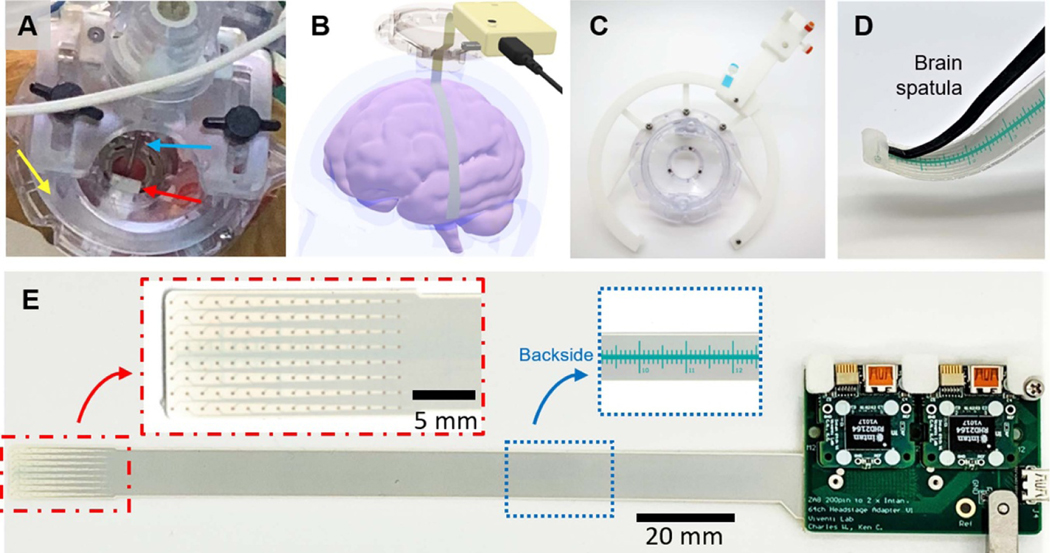
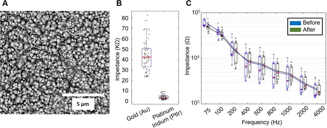
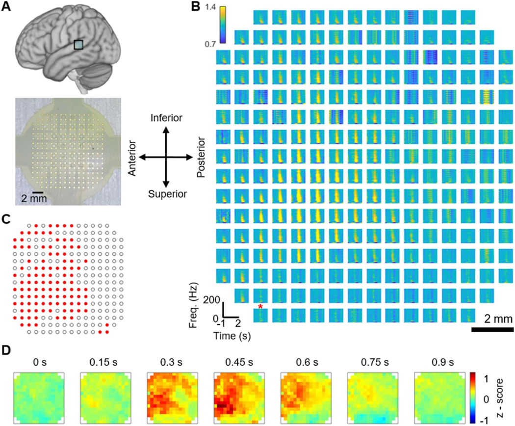
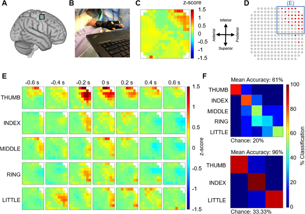
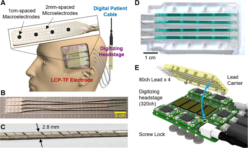
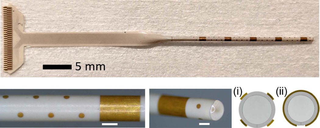
Objective.Brain functions such as perception, motor control, learning, and memory arise from the coordinated activity of neuronal assemblies distributed across multiple brain regions. While major progress has been made in understanding the function of individual neurons, circuit interactions remain poorly understood. A fundamental obstacle to deciphering circuit interactions is the limited availability of research tools to observe and manipulate the activity of large, distributed neuronal populations in humans. Here we describe the development, validation, and dissemination of flexible, high-resolution, thin-film (TF) electrodes for recording neural activity in animals and humans.Approach.We leveraged standard flexible printed-circuit manufacturing processes to build high-resolution TF electrode arrays. We used biocompatible materials to form the substrate (liquid crystal polymer; LCP), metals (Au, PtIr, and Pd), molding (medical-grade silicone), and 3D-printed housing (nylon). We designed a custom, miniaturized, digitizing headstage to reduce the number of cables required to connect to the acquisition system and reduce the distance between the electrodes and the amplifiers. A custom mechanical system enabled the electrodes and headstages to be pre-assembled prior to sterilization, minimizing the setup time required in the operating room. PtIr electrode coatings lowered impedance and enabled stimulation. High-volume, commercial manufacturing enables cost-effective production of LCP-TF electrodes in large quantities.Main Results. Our LCP-TF arrays achieve 25× higher electrode density, 20× higher channel count, and 11× reduced stiffness than conventional clinical electrodes. We validated our LCP-TF electrodes in multiple human intraoperative recording sessions and have disseminated this technology to >10 research groups. Using these arrays, we have observed high-frequency neural activity with sub-millimeter resolution.Significance.Our LCP-TF electrodes will advance human neuroscience research and improve clinical care by enabling broad access to transformative, high-resolution electrode arrays.

Keywords: Brain Machine Interface (BMI); ECoG; LCP; Neural Interface; electrode; iEEG; intraoperative.


Figures

Figure 1.
Figure 1.
Five liquid crystal polymer (LCP) thin-film (TF) electrode designs with varied coverage and high-density electrode spacing designed for use in rodents, non-human primates (NHP) and humans. (Top) Photos of electrode arrays. The 61 and 244ch arrays use zero insertion force (ZIF) connectors and the 80, 128, and 256ch arrays use ultra-low profile, high-density (0.8 mm pitch) spring connectors. Both connector designs do not require soldering or post-manufacturing assembly. The 80ch electrode array incorporates a hybrid design with four clinical standard macroelectrodes interspersed with 76 microelectrodes. (Bottom) Table of electrode specifications. The same LCP-TF manufacturing process can be used to simultaneously fabricate large and small electrode array designs.
Figure 2.
Figure 2.
Electrode cross section. (A) Photo of an electrode contact on a 61ch array. The yellow dashed line indicates the cross-section shown in (B) and (C). (B) Illustration of the electrode array layer stack-up. The electrode array wiring was embedded between the the LCP core and cover layers. The electrode contacts were flush with or slightly protruded from the surface of the LCP substrate. (C) Microscope photo of an example LCP-TF electrode array cross-section showing embedded wiring and an electrode contact. Two LCP sheets were thermally fused to form a single uniform LCP layer without a distinguishable border or fusion point.
Figure 3.
Figure 3.
3D illustration of the ultra-low profile, high-density (0.8 mm pitch) spring connector. The LCP-TF electrode array design included four alignment holes and a stiffener to increase the thickness and rigidity of the device in the connector area. The alignment holes and stiffener were standard features of the LCP flexible circuit process. (Inset) A side view of the spring connector highlighting the metal springs on the top and bottom of the connector.
Figure 4.
Figure 4.
Silicone electrode array molding procedure to combine multiple LCP-TF arrays together and provide soft edges to prevent damage to the cortex. (A) Illustrations of the electrode molding process. 1. Silicone primer was applied on the back side of the electrode and dried at room temperature for 30 min. 2. Double-sided polyimide tape was used to hold the alignment guide to the molding base. Double-sided transparent water soluble tape (PVA) was attached to the mold and the LCP-TF array to prevent silicone from covering the electrode contacts. A stencil was used to determine the shape and thickness of the silicone mold. 3. The LCP-TF array(s) were aligned and laminated onto the PVA tape using the alignment guide. 4. Well-mixed and degassed silicone was poured onto the mold. A wiper used to remove excessive silicone. 5. The silicone was cured at 60 °C for 2 h. 6. The assembly was soaked and rinsed with warm (>40 °C) DI water to remove the PVA tape and release the molded array. (B) SEM image of the cross section of a molded array showing the flat surface at the transition from the LCP-TF to silicone. Dust on the surface and side of the array were generated from the cross-sectional cut and not present normally. (C) Profilometer measurements of the electrode contact step height (Site) and the surface of the LCP-TF to silicone transition (Edge) showed a much flatter surface profile than conventional subdural clinical electrodes. (D) The LCP-TF prototype device was ∼11× less stiff than the commercial ECoG array. Maximum possible bending force that could be exerted on the brain derived from four-point bending tests and an analysis of brain geometry. A commercially available electrode array as well as an LCP-TF device prototype without Au traces were measured. The error bars indicate a standard error of means for all bending angles tested. The mean and SEM force for the LCP-TF prototype device was 6 ± 1 mN, while the commercial ECoG array force was 67 ± 17 mN.
Figure 5.
Figure 5.
Modular data acquisition system. (A) Photograph of custom digitizing headstage utilizing the Intan RHD2164 chip. This headstage can be connected through commonly used Omnetics connector or a standard micro-HDMI cable. (B) Modular adapter boards were fabricated to attach the digitizing headstage to the five different LCP-TF electrode designs. Red rectangles denote the position and the size of the digitizing headstage when connected. The 320ch system is designed for short-term implantation that uses 4× 80ch arrays to cover 4 × 4 cm2 of the cortex.
Figure 6.
Figure 6.
Intraoperative recording setup for open craniotomy procedures. (A) A flexible arm was used to hold the 244ch setup on top the craniotomy. Custom digitizing headstages were attached to the LCP-TF array and mounted to a metal base inside the 3D printed cap. The headstages were located as close as possible to the electrode array to reduce the effect of environmental noise sources. (B) Modular adapter PCBs were secured to the metal frame with screws. The metal base was also used to share the ground and reference among the four digitizing headstages. (C) 3D printed cases were used to protect the electrode and electronics during sterilization and handing. Slot openings (red arrows) were added to ensure the sterilization gas reached every component. (D) The recording setup can be scaled up to 1024ch. (E) The 1024ch electrode consisted of four 256ch array molded together to cover a 4 × 8 cm2 cortical area. The inset shows detail of the electrode contacts, which were 200 μm in diameter and spaced 1.7 mm apart. Holes were added wherever possible to the design to increase flexibility.
Figure 7.
Figure 7.
Intraoperative recording setup for experimental access through a burr hole. (A) Photograph of the experiment. An LCP-TF electrode (red arrow) was inserted through burr hole during a deep brain stimulation (DBS) surgery. The DBS base (Nexframe, yellow arrow) and lead (blue arrow) were used without any obstruction. (B) 3D rendering illustrates that the electrode was advanced under the dura more than 80 mm away from the burr hole, reaching the temporal lobe during a language study. (C) A custom 3D printed track system helped to hold the electronics at any angle from the implant site. (D) A pocket was molded at the tip of the electrode array to allowing a malleable brain retractor (brain spatula) to be used as an insertion tool to guide the electrode placement. (E) Photograph of the assembled LCP-TF array and recording system. Two digitizing headstages were connected to the modular adaptor board, requiring only a single μHDMI cable to be connected to the recording controller. Red inset shows the detailed view of the 128 electrode contacts. Blue inset shows the ruler, printed with biocompatible soldermask, on the back side of the LCP-TF electrode. The ruler was used to provide the surgeon relative position information while advancing the array under the dura.
Figure 8.
Figure 8.
LCP-TF electrodes were electroplated with platinum iridium (PtIr) to reduce electrode impedance and enable stimulation. (A) SEM picture of the PtIr-plated electrode surface. (B) Impedance measurement comparing gold electrodes (44 ± 13.9 kΩ) before PtIr coating and after (4.6 ± 1.8 kΩ) at 1 kHz. The red line in the boxplot indicates the median value. All data points are shown as the dots within the box plot (N = 60). (C) Electrode impedance spectroscopy (EIS) measurements of 12 electrodes taken before and after 1 M pulses of biphasic stimulation at 100 μs per phase, 124 μA, and 50 Hz repetition rate showed no change in electrode impedance. The lines are the average impedances. No damage to the electrode contacts was observed.
Figure 9.
Figure 9.
Example LCP-TF electrode human intraoperative recording to study speech and language. (A) A 244-channel LCP-TF electrode array (bottom) recorded auditory responses from the posterior superior temporal gyrus (pSTG—top) in a patient undergoing treatment for pharmacologically resistant epilepsy. The patient was asleep during the auditory stimulus (words and non-words) presentation. The in vivo electrode impedance data can be found in supplemental figure 3. (B) Spectrograms for the local field from each channel (right) show auditory responses on selective channels. These responses were mainly found in the high gamma (HG) frequency range (70–150 Hz), shown to be a correlate of multi-unit neuronal firing. The red star denoted the high impedance channel. (C) The red channels exhibit significant high-gamma responses during auditory onset relative to baseline (one-sided permutation test, p < 0.05, FDR corrected). (D) Normalized HG time-series heat maps show the spatial detail of the auditory response.
Figure 10.
Figure 10.
Example LCP-TF electrode human intraoperative recording to study motor responses. (A) A 244-ch LCP-TF electrode array recorded neural activity during voluntary finger movement from the ‘hand-knob’ region of the motor cortex of a patient undergoing tumor resection. The electrode impedance data for this array can be found in supplemental figure 4. (B) The participant performed a finger movement task following visually presented cues. The finger kinematics were recorded using a data glove. (C) Normalized high gamma (HG) responses (70–150 Hz; maximum values from −500 ms to 500 ms at movement onset) revealed spatial features of the finger movements focused on the top right corner of the array. (D) A statistical analysis (one-sided permutation test) was performed to determine the channels with significant HG responses during movement onset relative to baseline (p < 0.05, FDR corrected). The blue box indicates the 8 × 8 area of the array that is the focus for panel E. (E) Spatial maps of normalized high-gamma responses separated by finger types during movement. 0 s indicates the onset of finger movement from the glove data. (F) Finger flexion decoding using a linear classification scheme (leave-one-out cross-validation) obtained 61% and 96% classification accuracies for five-finger and three-finger decoders, respectively.
Figure 11.
Figure 11.
LCP-TF electrode and recording system design for human short-term implantation. (A) The LCP-TF electrode can be placed through a small craniotomy and advanced under the skull. Our LCP-TF semi-chronic system includes conventional 2.3 mm diameter macroelectrodes spaced 10 mm apart and 200 μm diameter microelectrodes spaced 2 mm apart. Coiled leads were designed to be tunneled out of the scalp using a cannula and connected to the digitizing headstage. The digitizing headstage provides signal amplification and digitization in the patient head bandages. (B) Assembled and molded LCP-TF electrode array with 16 macro- and 304 microcontacts. (C) The coiled leads were molded to a 2.8 mm diameter cable, in order to fit into a standard 3 mm diameter cannula. (D) A custom lead carrier was designed to assist the alignment of the leads to the spring connector. (E) Detailed view of the design of the high-density connector system to the digitizing headstage, showing the connector alignment and connecting mechanism.
Figure 12.
Figure 12.
LCP-TF SEEG prototype includes 56 microelectrodes with 500 μm spacing and five macroelectrodes with 5 mm spacing. The physical form factor is the same as standard clinical SEEG electrodes (900 μm diameter), making it compatible with existing clinical workflows. Cross sectional drawings illustrate the arrangement of four microelectrodes around the circumference of the array (i), while the macroelectrodes wrap around the entire array (ii).

References

    1. Bergey GK et al. 2015. Long-term treatment with responsive brain stimulation in adults with refractory partial seizures Neurology 84 810–7 - PMC - PubMed
    1. Benabid AL et al. 2019. An exoskeleton controlled by an epidural wireless brain–machine interface in a tetraplegic patient: a proof-of-concept demonstration Lancet Neurol. 18 1112–22 - PubMed
    1. Shokoueinejad M. et al. Progress in the field of micro-electrocorticography. Micromachines. 2019;10:62. - PMC - PubMed
    1. Brodnick SK. et al. μECoG recordings through a thinned skull. Front. Neurosci. 2019;13:1017. - PMC - PubMed
    1. Slutzky MW, Jordan LR, Krieg T, Chen M, Mogul DJ and Miller LE 2010. Optimal spacing of surface electrode arrays for brain–machine interface applications J. Neural. Eng 7 26004. - PMC - PubMed

Publication types

Substances

LinkOut - more resources