. 2021 Jun 4;18(4):10.1088/1741-2552/ac038b.
doi: 10.1088/1741-2552/ac038b.

Electrochemical safety limits for clinical stimulation investigated using depth and strip electrodes in the pig brain

Affiliations

Electrochemical safety limits for clinical stimulation investigated using depth and strip electrodes in the pig brain

Ritwik Vatsyayan et al. J Neural Eng. .

Abstract

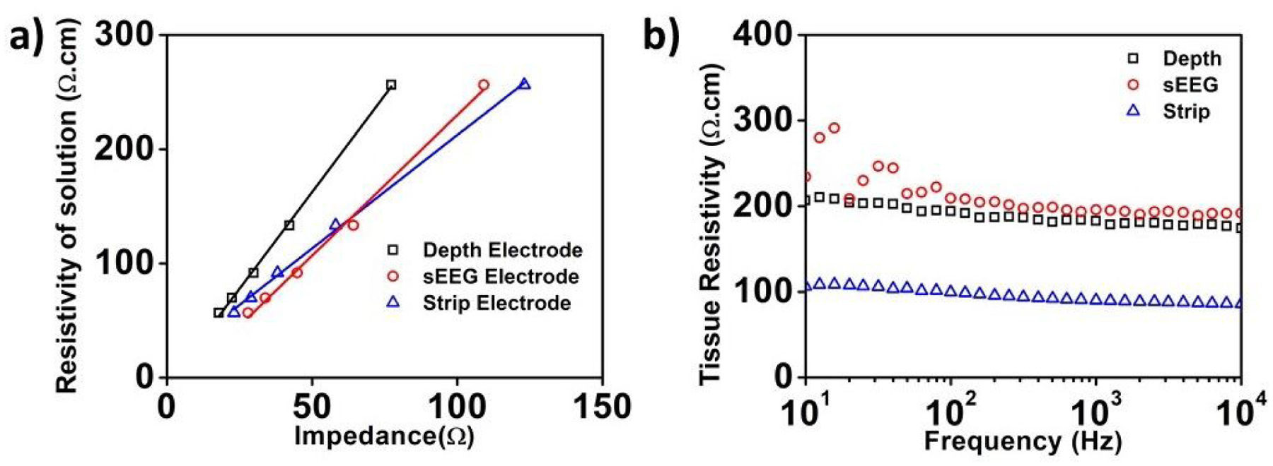
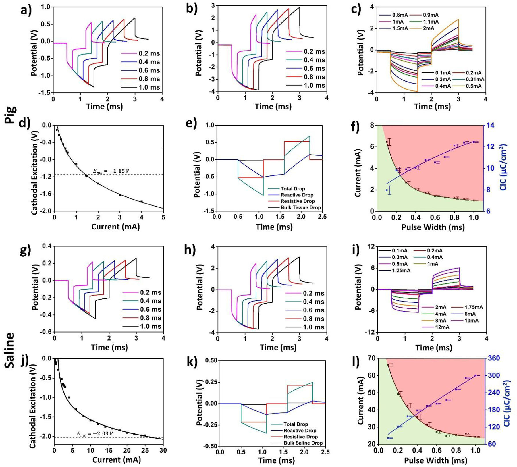
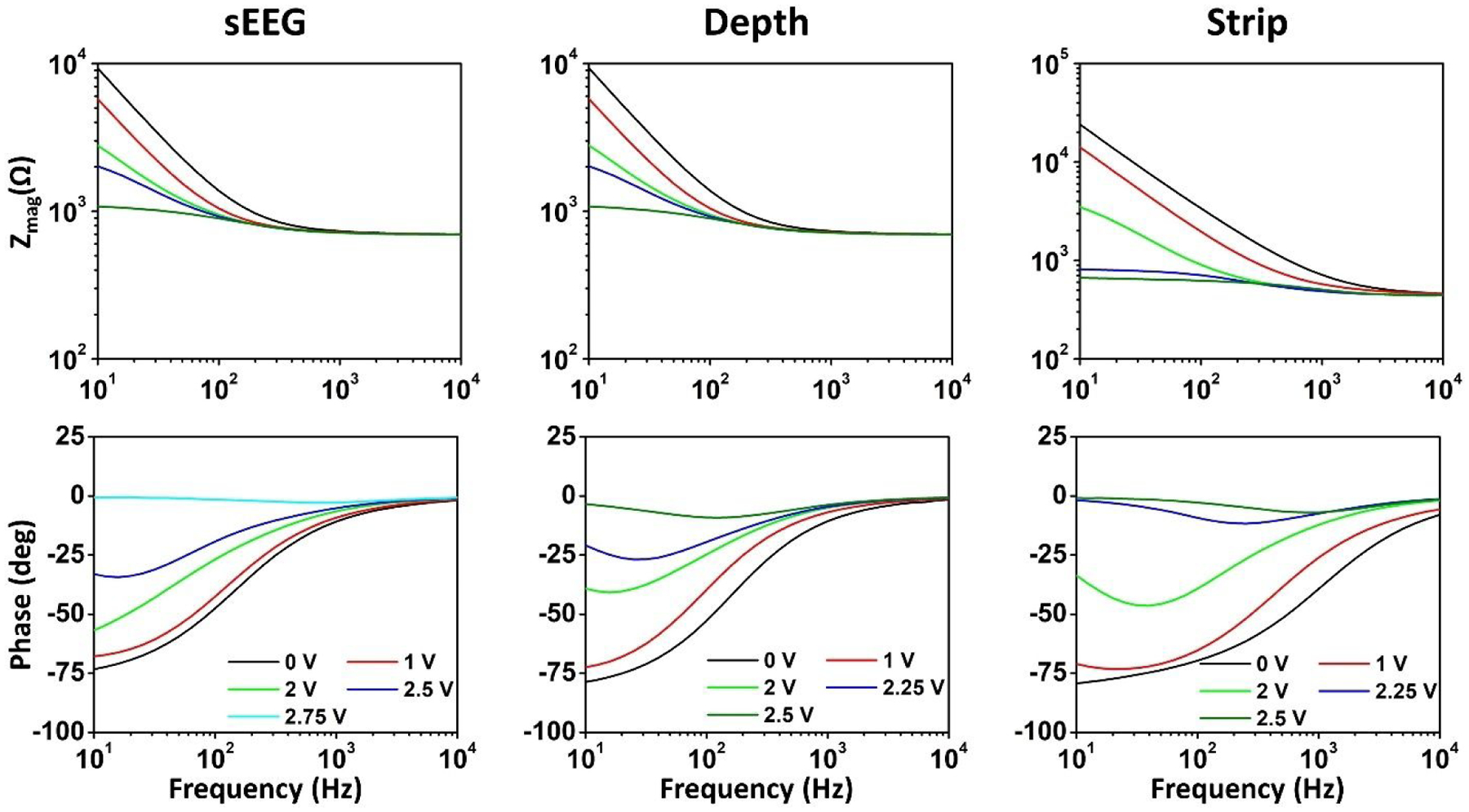
Objective. Diagnostic and therapeutic electrical stimulation are increasingly utilized with the rise of neuromodulation devices. However, systematic investigations that depict the practical clinical stimulation paradigms (bipolar, two-electrode configuration) to determine the safety limits are currently lacking. Further, safe charge densities that were classically determined from conical sharp electrodes are generalized for cylindrical (depth) and flat (surface grid) electrodes completely ignoring geometric factors that govern current spreading and trajectories in tissue.Approach. This work reports the first investigations comparing stimulation limits for clinically used electrodes in two mediums: in benchtop experiments in saline andin vivoin a single acute experiment in the pig brain. We experimentally determine the geometric factors, the water electrolysis windows, and the current safety limits from voltage transients, for the sEEG, depth and surface strip electrodes in both mediums. Using four-electrode and three-electrode configuration measurements and comprehensive circuit models that accurately depict our measurements, we delineate the various elements of the stimulation medium, including the tissue-electrode interface impedance spectra, the medium impedance and the bias-dependent change in the interface impedance as a function of stimulation parameters.Main results. The results of our systematics studies suggest that safe currents in clinical bipolar stimulation determinedin vivocan be as much as 24 times smaller than those determined from benchtop experiments (for depth electrodes at a 1 ms pulse duration). Our detailed circuit modeling attributes this drastic difference in safe limits to the greatly dissimilar electrode/tissue and electrode/saline impedances.Significance. We established the electrochemical safety limits for commonly used clinical electrodesin vivoand revealed by detailied electrochemical modeling how they differ from benchtop evaluation. We argue that electrochemical limits and currents are unique for each electrode, should be measuredin vivoaccording to the protocols established in this work, and should be accounted for while setting the stimulation parameters for clinical applications including for chronic applications.

Keywords: brain; clinical; electrochemical; electrode; limits; safety; stimulation.


Figures

Figure 1:
Figure 1:
Experimental configurations for the electrochemical assessment and the subdural electrode placement in the pig’s brain. W-Working electrode, WS- Working Sense electrode, R- Reference electrode, C- Counter electrode. (a) 2-electrode impedance breakout (b) 3-electrode impedance breakout (c) 4-electrode impedance breakout (d) sEEG electrode placement (e) Depth electrode insertion and placement (f) Strip electrode insertion and placement. Grayed box and text indicate negligible contribution.
Figure 2:
Figure 2:
Electrochemical impedance spectroscopy composed to impedance magnitude (top panel) and phase (bottom panel) in the pig (a,c,e) and saline (b,d,f) for the sEEG electrode (a,b), for the depth electrode (c,d) and the strip electrode (e,f).
Figure 3:
Figure 3:
(a) Extraction of the electrode geometric correction factor for the three types of electrodes used in this study. (b) Extracted tissue resistivity for the pig’s brain as a function of frequency using the 4-point probe measurements for the three different electrodes.
Figure 4:
Figure 4:
Approximate circuit model for the (a) 2-electrode (b) 3-electrode (c) 4-electrode measurement configurations used for simulations in Cadence Spectre. The inset for the Constant Phase Element is an approximate circuit model used for simulations. An RC ladder with 10 RC branches was used in our circuit model. The measured and simulated voltage transients in the pig cortical tissue (d–f) and saline (g–i) for (d,g) sEEG, (e,h) depth, and (f,i) strip electrodes are plotted for the verification of our model.
Figure 5:
Figure 5:. Voltage transients, current, and charge injection limits in the pig’s brain
(a)–(f) and saline (g)–(l) for the sEEG electrode. (a), (g) The voltage transients for a 0.5 mA injected current at varying pulse-widths. (b), (h) Voltage transients for a 2mA injected current at varying pulse widths. (c), (i) Voltage transients for a 600μs pulse width for varying current amplitudes. (d), (j) Plot the cathodal excitation as a function of the injected current for a 600μs pulse width. (e), (k) Total and individual potential drops across the resistive and reactive elements of the electrode-tissue interface, and across the tissue. (f), (l) Variation in the safe current injection level and CIC with pulse width, with the green shaded area representing the safe stimulation regime. Error bars in panels (f) and (l) represent the normalized root-mean square error from the curve fitting of the cathodal excitation as a function of current.
Figure 6:
Figure 6:. Voltage transients, current, and charge injection limits in the pig’s brain
(a)–(f) and saline (g)–(l) for the depth electrode. (a), (g) The voltage transients for a 0.5 mA injected current at varying pulse-widths. (b), (h) Voltage transients for a 2mA injected current at varying pulse widths. (c), (i) Voltage transients for a 600μs pulse width for varying current amplitudes. (d), (j) Plot the cathodal excitation as a function of the injected current for a 600μs pulse width. (e), (k) Total and individual potential drops across the resistive and reactive elements of the electrode-tissue interface, and across the tissue. (f), (l) Variation in the safe current injection level and CIC with pulse width, with the green shaded area representing the safe stimulation regime. Error bars in panels (f) and (l) represent the normalized root-mean square error from the curve fitting of the cathodal excitation as a function of current.
Figure 7:
Figure 7:. Voltage transients, current, and charge injection limits in the pig’s brain
(a)–(f) and saline (g)–(l) for the strip electrode. (a), (g) The voltage transients for a 0.5 mA injected current at varying pulse-widths. (b), (h) Voltage transients for a 2mA injected current at varying pulse widths. (c), (i) Voltage transients for a 600μs pulse width for varying current amplitudes. (d), (j) Plot the cathodal excitation as a function of the injected current for a 600μs pulse width. (e), (k) Total and individual potential drops across the resistive and reactive elements of the electrode-tissue interface, and across the tissue. (f), (l) Variation in the safe current injection level and CIC with pulse width, with the green shaded area representing the safe stimulation regime. Error bars in panels (f) and (l) represent the normalized root-mean square error from the curve fitting of the cathodal excitation as a function of current.
Figure 8:
Figure 8:
Cathodal Excitation as a function of the injected current for different pulse widths for each electrode in-vivo and in saline.
Figure 9:
Figure 9:
Shannon Limit for the extracted CIC compared against previously reported tissue damage thresholds, marked with open symbols. Filled squares represent the electrochemical safety limits obtained in the present study. The dashed line for k=1.85 represents the tissue damage threshold from prior studies, and the dashed line for k=0.9 represent the electrochemical safety limit for depth electrode obtained in this study. Multiple data points from tissue damage thresholds and electrochemical safety limits fall below the k=1.85 established tissue damage threshold by the Shannon equation.
Figure 10:
Figure 10:
Measured impedance spectra as a function of the applied potential bias on the working electrode for the three types of electrodes in benchtop experiments.
Figure 11:
Figure 11:
A summary of the stimulation limits calculated from in-vivo experiments in pig cortical tissue and benchtop experiments in saline for the (a) sEEG, (b) Depth and (c) Strip electrodes. We observe significant reduction in the in-vivo stimulation limits for all three types of electrodes.

References

    1. Agnew WF, Yuen TGH and McCreery DB (1983) ‘Morphologic changes after prolonged electrical stimulation of the cat’s cortex at defined charge densities’, Experimental Neurology, 79(2), pp. 397–411. doi: 10.1016/0014-4886(83)90221-2. - DOI - PubMed
    1. Alba NA et al. (2015) ‘In vivo electrochemical analysis of a PEDOT/MWCNT neural electrode coating’, Biosensors, 5(4), pp. 618–646. doi: 10.3390/bios5040618. - DOI - PMC - PubMed
    1. Bai SJ and Prinz FB (2011) ‘In vivo electrochemical impedance measurement on single cell membrane’, Microelectronic Engineering, 88(10), pp. 3094–3100. doi: 10.1016/j.mee.2011.06.003. - DOI
    1. Bao JZ, Lu ST and Hurt WD (1997) ‘Complex dielectric measurements and analysis of brain tissues in the radio and microwave frequencies’, IEEE Transactions on Microwave Theory and Techniques, 45(10 PART 1), pp. 1730–1741. doi: 10.1109/22.641720. - DOI
    1. Bisquert J et al. (1998) ‘Impedance of constant phase element (CPE)-blocked diffusion in film electrodes’, Journal of Electroanalytical Chemistry, 452(2), pp. 229–234. doi: 10.1016/S0022-0728(98)00115-6. - DOI

Publication types

LinkOut - more resources