

Enhanced condensation heat transfer using porous silica inverse opal coatings on copper tubes
- PMID: 34021211
- PMCID: PMC8140112
- DOI: 10.1038/s41598-021-90015-x
Enhanced condensation heat transfer using porous silica inverse opal coatings on copper tubes
Abstract
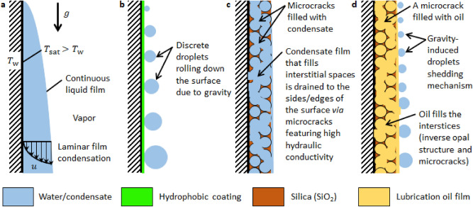
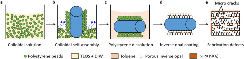
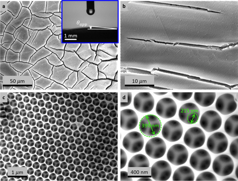
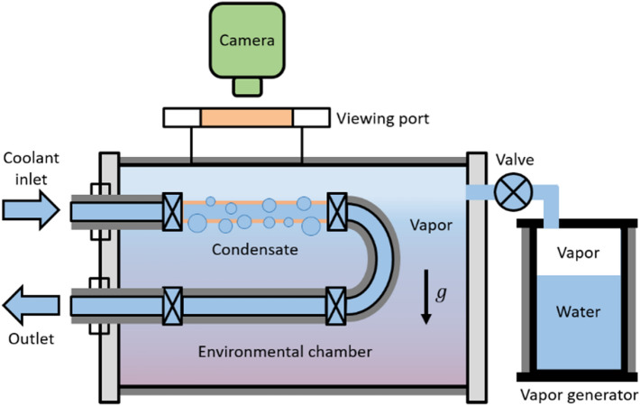
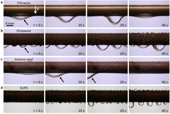
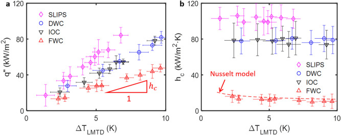
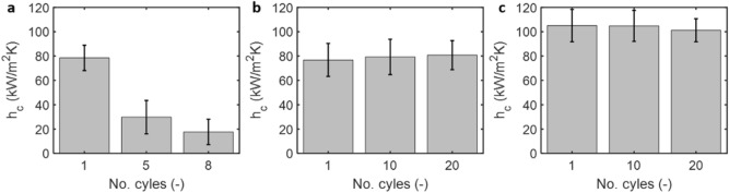
Phase-change condensation is commonplace in nature and industry. Since the 1930s, it is well understood that vapor condenses in filmwise mode on clean metallic surfaces whereas it condenses by forming discrete droplets on surfaces coated with a promoter material. In both filmwise and dropwise modes, the condensate is removed when gravity overcomes pinning forces. In this work, we show rapid condensate transport through cracks that formed due to material shrinkage when a copper tube is coated with silica inverse opal structures. Importantly, the high hydraulic conductivity of the cracks promote axial condensate transport that is beneficial for condensation heat transfer. In our experiments, the cracks improved the heat transfer coefficient from ≈ 12 kW/m2 K for laminar filmwise condensation on smooth clean copper tubes to ≈ 80 kW/m2 K for inverse opal coated copper tubes; nearly a sevenfold increase from filmwise condensation and identical enhancement with state-of-the-art dropwise condensation. Furthermore, our results show that impregnating the porous structure with oil further improves the heat transfer coefficient by an additional 30% to ≈ 103 kW/m2 K. Importantly, compared to the fast-degrading dropwise condensation, the inverse opal coated copper tubes maintained high heat transfer rates when the experiments were repeated > 20 times; each experiment lasting 3-4 h. In addition to the new coating approach, the insights gained from this work present a strategy to minimize oil depletion during condensation from lubricated surfaces.
Conflict of interest statement
The authors declare no competing interests.
Figures

Similar articles
-
Depletion of Lubricant from Nanostructured Oil-Infused Surfaces by Pendant Condensate Droplets.ACS Nano. 2020 Jul 28;14(7):8024-8035. doi: 10.1021/acsnano.9b10184. Epub 2020 Jun 17. ACS Nano. 2020. PMID: 32490664
-
Capillary-Enhanced Filmwise Condensation in Porous Media.Langmuir. 2018 Nov 20;34(46):13855-13863. doi: 10.1021/acs.langmuir.8b02611. Epub 2018 Nov 8. Langmuir. 2018. PMID: 30372087
-
Scalable graphene coatings for enhanced condensation heat transfer.Nano Lett. 2015 May 13;15(5):2902-9. doi: 10.1021/nl504628s. Epub 2015 Apr 8. Nano Lett. 2015. PMID: 25826223
-
Condensation heat transfer in microgravity conditions.NPJ Microgravity. 2023 Apr 4;9(1):32. doi: 10.1038/s41526-023-00276-1. NPJ Microgravity. 2023. PMID: 37015948 Free PMC article. Review.
-
Bioinspired Superwettability Surface Strategies for Condensation Heat Transfer.ACS Nano. 2025 Feb 4;19(4):4156-4169. doi: 10.1021/acsnano.4c17632. Epub 2025 Jan 27. ACS Nano. 2025. PMID: 39868532 Review.
Cited by
-
Direct Measurement and Modeling of Wrapping Layer on Lubricant-Infused Surfaces.ACS Appl Mater Interfaces. 2025 Aug 27;17(34):48895-48903. doi: 10.1021/acsami.5c09883. Epub 2025 Aug 14. ACS Appl Mater Interfaces. 2025. PMID: 40810421 Free PMC article.
-
The influence of Nusselt number on dropwise condensation heat transfer for a single droplet on inclined and grooved surfaces.Sci Rep. 2025 Jan 2;15(1):527. doi: 10.1038/s41598-024-84127-3. Sci Rep. 2025. PMID: 39747523 Free PMC article.
-
Slippery liquid infused porous surface (SLIPS) condensers for high efficiency air gap membrane distillation.Commun Eng. 2025 Mar 15;4(1):48. doi: 10.1038/s44172-025-00348-y. Commun Eng. 2025. PMID: 40089632 Free PMC article.
-
Visualization and Experimental Characterization of Wrapping Layer Using Planar Laser-Induced Fluorescence.ACS Nano. 2024 Feb 6;18(5):4068-4076. doi: 10.1021/acsnano.3c07407. Epub 2024 Jan 26. ACS Nano. 2024. PMID: 38277478 Free PMC article.
-
Enhancing Liquid-Vapor Phase-Change Heat Transfer with Micro/Nano-Structured Surfaces.ACS Nano. 2025 Mar 18;19(10):9513-9589. doi: 10.1021/acsnano.4c15277. Epub 2025 Mar 10. ACS Nano. 2025. PMID: 40062720 Free PMC article. Review.
References
-
- Beér JM. High efficiency electric power generation: The environmental role. Prog. Energy Combust. Sci. 2007;33:107–134. doi: 10.1016/j.pecs.2006.08.002. - DOI
-
- Hung T-C, Shai T, Wang SK. A review of organic Rankine cycles (ORCs) for the recovery of low-grade waste heat. Energy. 1997;22:661–667. doi: 10.1016/S0360-5442(96)00165-X. - DOI
-
- Reifert V, Sardak A, Grigorenko S, Podbereznyj V. Heat exchange at dropwise condensation in heat exchangers of desalination plants. Desalination. 1989;74:373–382. doi: 10.1016/0011-9164(89)85064-7. - DOI
-
- Luijten C, Van Hooy R, Janssen J, Van Dongen M. Multicomponent nucleation and droplet growth in natural gas. J. Chem. Phys. 1998;109:3553–3558. doi: 10.1063/1.476950. - DOI
-
- Khawaji AD, Kutubkhanah IK, Wie J-M. Advances in seawater desalination technologies. Desalination. 2008;221:47–69. doi: 10.1016/j.desal.2007.01.067. - DOI
Grants and funding
- N00014-17-1-2913/Office of Naval Research, U.S. Department of Defense
- DMR 1420570/NSF Materials Research Science and Engineering Center (MRSEC) at Harvard University
- DE-AR0000326/Advanced Research Projects Agency-Energy, U.S. Department of Energy
- ECS 0335765/Harvard Center for Nanoscale Systems supported by the NSF
LinkOut - more resources
Full Text Sources
Other Literature Sources
