. 2021 Jun;82(3):321-332.
doi: 10.1055/s-0039-1700513. Epub 2019 Oct 28.

Anatomical Step-by-Step Dissection of Complex Skull Base Approaches for Trainees: Surgical Anatomy of the Retrosigmoid Approach

Affiliations

Anatomical Step-by-Step Dissection of Complex Skull Base Approaches for Trainees: Surgical Anatomy of the Retrosigmoid Approach

Christopher S Graffeo et al. J Neurol Surg B Skull Base. 2021 Jun.

Abstract

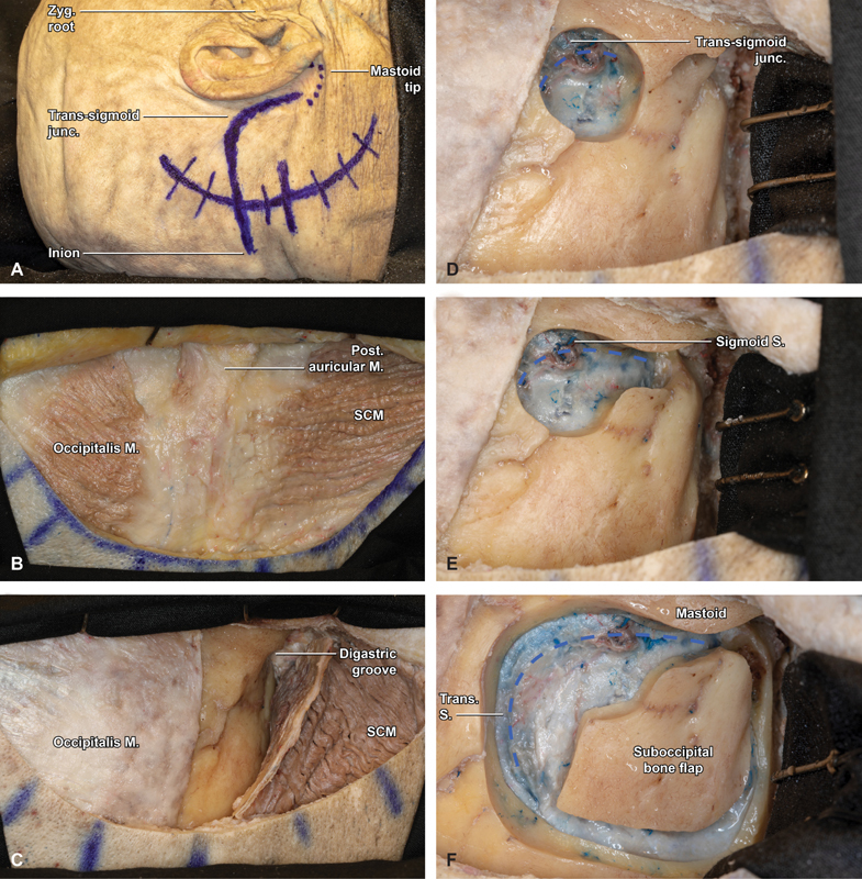
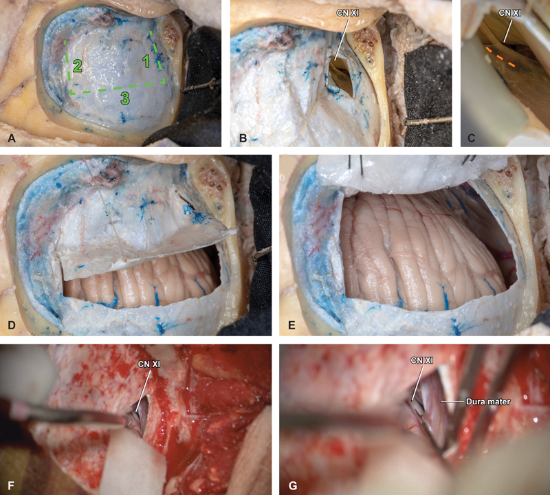
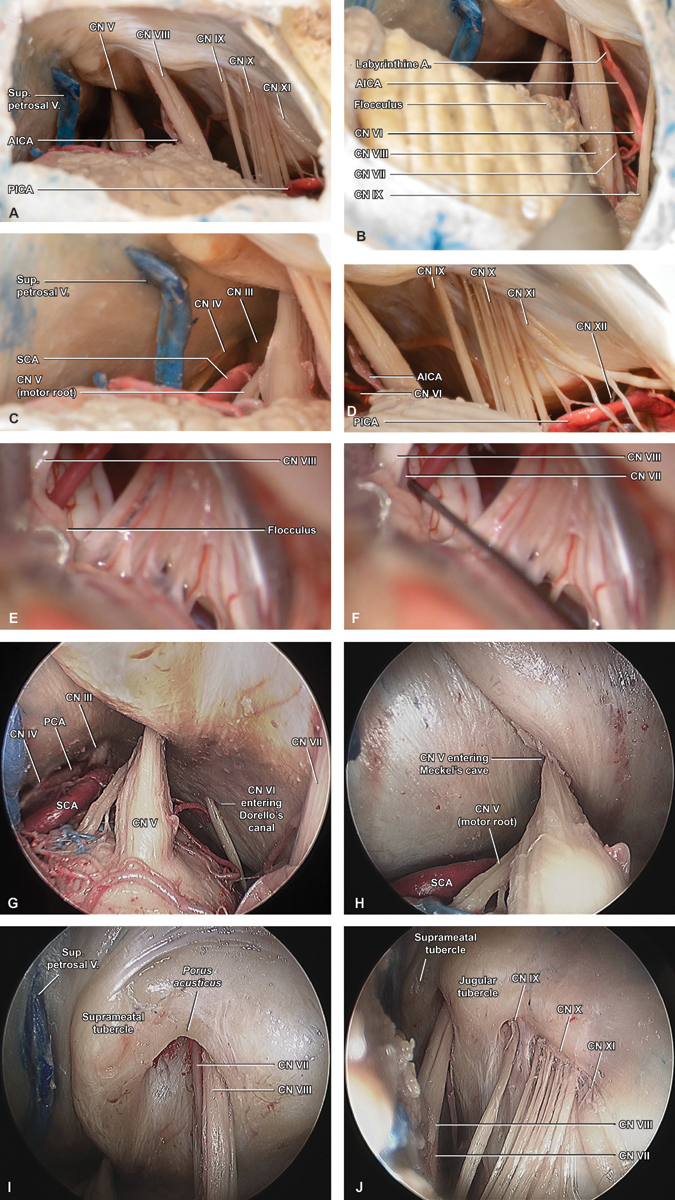
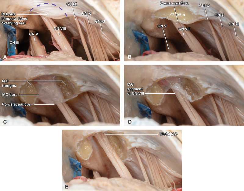
Introduction Neurosurgical anatomy is traditionally taught via anatomic and operative atlases; however, these resources present the skull base using views that emphasize three-dimensional (3D) relationships rather than operative perspectives, and are frequently written above a typical resident's understanding. Our objective is to describe, step-by-step, a retrosigmoid approach dissection, in a way that is educationally valuable for trainees at numerous levels. Methods Six sides of three formalin-fixed latex-injected specimens were dissected under microscopic magnification. A retrosigmoid was performed by each of three neurosurgery residents, under supervision by the senior authors (C.L.W.D. and M.J.L.) and a graduated skull base fellow, neurosurgeon, and neuroanatomist (M.P.C.). Dissections were supplemented with representative case applications. Results The retrosigmoid craniotomy (aka lateral suboccipital approach) affords excellent access to cranial nerve (CN) IV to XII, with corresponding applicability to numerous posterior fossa operations. Key steps include positioning and skin incision, scalp and muscle flaps, burr hole and parasigmoid trough, craniotomy flap elevation, initial durotomy and deep cistern access, completion durotomy, and final exposure. Conclusion The retrosigmoid craniotomy is a workhorse skull base exposure, particularly for lesions located predominantly in the cerebellopontine angle. Operatively oriented neuroanatomy dissections provide trainees with a critical foundation for learning this fundamental skull base technique. We outline a comprehensive approach for neurosurgery residents to develop their familiarity with the retrosigmoid craniotomy in the cadaver laboratory in a way that simultaneously informs rapid learning in the operating room, and an understanding of its potential for wide clinical application to skull base diseases.

Keywords: acoustic neuroma; education; meningioma; retrosigmoid; simulation; skull base; vestibular schwannoma.


Conflict of interest statement

Conflict of Interest None declared.

Figures

Fig. 1
Fig. 1
Step-by-step retrosigmoid craniotomy in an anatomical specimen (right side). ( A ) Marked skin incision approximately 5-cm posterior to the digastric notch (6-cm posterior to the helix). The transverse sinus is approximated by connecting an imaginary line from the inion to the zygomatic root, while the sigmoid follows the digastric groove. ( B ) With the postauricular scalp flap reflected anterior, the underlying musculature is visualized, including the occipitalis, posterior auricular, and sternocleidomastoid (SCM) muscles. ( C ) Three cuts are made in SCM roughly paralleling the digastric groove, SCM insertion, and medial margin of the skin incision. ( D ) With the SCM flap protected, reflected inferiorly, and secured with 2 fish hooks, a large burr hole is fashioned overlying the transverse sigmoid junction (blue hash). ( E ) Bone removal is carried from the burr hole inferiorly, tracing the course of the sigmoid sinus to the level of the mastoid tip (blue hash). ( F ) After carefully and extensively stripping the dura from the inner table of the occipital bone, a small, rectangular bone flap is turned with the spiral bit and footplate attachment, with the superior and lateral bony exposure revealing the margins of the transverse and sigmoid sinuses (blue hash). Junc, junction; M, muscle; Post, posterior; S, sinus; SCM, sternocleidomastoid; Trans, transverse; Zyg, zygomatic.
Fig. 2
Fig. 2
Dural opening and cisterna magna access. ( A ) With the bone flap removed, a trap-door durotomy is planned in three cuts, with the base abutting the sigmoid sinus and the superior cut placed approximately 1 to 2 mm inferior to the inferior margin of the transverse sinus. ( B ) The inferior cut is made first, 5 mm above the inferior bony margin at the posterior border of the descending sigmoid sinus. This small initial dural opening facilitates early foramen magnum access and CSF drainage, to achieve posterior fossa relaxation. Within the deep, inferior aspect of the intradural space, the spinal component of cranial nerve XI is visualized ascending through the foramen magnum. ( C ) Safe opening of the arachnoid is best performed sharply, just posterior to the ascending nerve (orange hash). ( D ) The medial and superior cuts are performed in a stepwise fashion and the dural flap is elevated carefully, ( E ) covered with an antibiotic-soaked nonadherent surgical strip pattie, and secured in place using 3–0 silk sutures. ( F ) Representative intraoperative photographs demonstrate the technique of using a ½” x 3” pattie and dynamic retraction to expose XI and ( G ) incise the overlying arachnoid. CN, cranial nerve.
Fig. 3
Fig. 3
Intradural exposure. ( A ) An initial overview of the final intradural exposure demonstrates how the retrosigmoid craniotomy allows for ready identification of cranial nerves V, VIII, IX, X, and XI, as well as the anterior and posterior inferior cerebellar arteries (AICA/PICA), and superior petrosal vein. ( B ) Gentle elevation of the cerebellar flocculus reveals cranial nerve VII at the brainstem root entry zone via the “infrafloccular maneuver,” while high-magnification views at the ( C ) superior and ( D ) inferior limits of the exposure highlight cranial nerves III and IV adjacent to the deep medial margin of the tentorium, and cranial nerve XII within the foramen magnum, where its rootlets are interdigitated with branches of PICA and the ipsilateral vertebral artery. ( E ) Intraoperative photographs prior to and ( F ) during an infrafloccular maneuver highlight how this technique allows for early identification and stimulation of VII. ( G ) Endoscopic images captured at 0-degree provide additional, close-up views of the upper retrosigmoid exposure, where cranial nerves III–VI are encountered, including VI entering Dorello's canal and ( H ) V entering Meckel's cave. ( I ) Adjacent endoscopic images captured inferiorly at 45-degree highlight the anatomic details surrounding the IAC and jugular foramen, including the relationship between cranial nerves VII and VIII at the porus acusticus , ( J ) as well as cranial nerves IX and X-XI at the jugular foramen. The root exit zone of VII is also appreciated, via this relative infra-floccular perspective. A, artery; AICA, anterior inferior cerebellar artery; CN, cranial nerve; PICA, posterior inferior cerebellar artery; Sup., superior; V, vein.
Fig. 4
Fig. 4
Internal auditory canal (IAC) drilling. ( A ) Intradural exposure of the IAC is initiated by removing a semilunar region of the medial petrous temporal bone (purple hash) overlying the porus acusticus ( B ), to a lateral depth based on IAC length, tumor extent and location of posterior semicircular canal. ( C ) With these boundaries established, saucerization of the region overlying the porus carefully proceeds until the IAC dura is identified overlying cranial nerve VIII. ( D ) Taking care to protect the IAC dura and contents, two troughs are extended at the superior and inferior limits of the region of bony removal and carried longitudinally from the porus to the fundus, and ( E ) deepened until at least 180 degrees of circumferential IAC exposure is completed. CN, cranial nerve; PCA, posterior cerebral artery; SCA, superior cerebellar artery; Sup., superior; V, vein.
Fig. 5
Fig. 5
Illustrative cases. ( A – case one ) Preoperative T1-weighted MRI slices in the axial and coronal planes demonstrate a large, heterogeneous, vividly enhancing CPA mass with IAC extension, most consistent with vestibular schwannoma. ( B – case one ) Comparable postoperative T1-weighted MRI slices in the axial and coronal planes confirm gross total resection of the lesion, as well as a small, contralateral, intracanalicular mass, diagnostic of NF-II (red arrow). ( C – case two ) Preoperative T1-weighted MRI slices in the axial and coronal planes identify a very large, homogenously enhancing, dural-based CPA mass extending from the tentorium to the foramen magnum and causing severe compression and displacement of the brainstem, consistent with a jugular foramen meningioma. ( D – case two ) Following resection, a small, anticipated tumor residuum was noted at the jugular foramen, with aggressive subtotal resection of all other tumor. ( E – case three ) Preoperative T2-weighted axial and coronal MRI identified a very large hyper-intense CPA mass causing dramatic midbrain compression and mass effect. Diffusion-weighted sequences demonstrated marked restricted diffusion, confirming the diagnosis of epidermoid cyst. ( F – case three ) Postoperative T2-weighted axial, T1-weighted coronal, and diffusion-weighted axial and coronal sequences confirmed gross total resection of the lesion, with interval improvement in midline shift of the midbrain and pons. CN, Cranial nerve; CPA, cerebellopontine angle; IAC, Internal auditory canal; MRI, magnetic resonance imaging; NF, neurofibromatosis.
Fig. 6
Fig. 6
Presigmoid versus retrosigmoid trajectories. ( A ) Extensive dissection of a neuroanatomic specimen centered on the lateral skull base and sigmoid sinus region highlights the relative trajectories afforded by retrosigmoid (*) versus presigmoid (**) approaches to the CPA. Although the dura forming Trautman's triangle between the sinus, bony labyrinth, and superior petrosal sinus has been removed, the very high position of the jugular bulb in this specimen would markedly limit a presigmoid approach in a patient with similar anatomy. ( B ) Comparable dissection of a different neuroanatomic specimen demonstrates how a patient with a low-lying jugular bulb would constitute a more appropriate candidate for presigmoid in addition to retrosigmoid approaches. CPA, cerebellopontine angle.

References

    1. Meyer F B. Philadelphia, PA: Churchill Livingstone; 1999. Atlas of Neurosurgery: Basic Approaches to Cranial and Vascular Procedures.
    1. Tew J M, Van Loveren H Keller JT. Philadelphia, PA: Saunders; 1994. Atlas of Operative Microneurosurgery.
    1. Rhoton A L., JrThe cerebellopontine angle and posterior fossa cranial nerves by the retrosigmoid approach Neurosurgery 200047(3, Suppl):S93–S129. - PubMed
    1. Wanibuchi M, Friedman A H, Fukushima T. Stuttgart, Germany: Thieme; 2009. Photo Atlas of Skull Base Dissection: Techniques and Operative Approaches.
    1. Carlstrom L P, Perry A, Graffeo C S.Foundations of advanced neuroanatomy: technical guidelines for specimen preparation, dissection, and 3d-photodocumentation in a surgical anatomy laboratory J Neurol Surg B Skull Base 201980(S 01):S1–S244. - PMC - PubMed