. 2021 Jun 9;13(22):25589-25598.
doi: 10.1021/acsami.1c01984. Epub 2021 May 25.

Protein Micropatterning in 2.5D: An Approach to Investigate Cellular Responses in Multi-Cue Environments

Affiliations

Protein Micropatterning in 2.5D: An Approach to Investigate Cellular Responses in Multi-Cue Environments

Cas van der Putten et al. ACS Appl Mater Interfaces. .

Erratum in

Abstract

The extracellular microenvironment is an important regulator of cell functions. Numerous structural cues present in the cellular microenvironment, such as ligand distribution and substrate topography, have been shown to influence cell behavior. However, the roles of these cues are often studied individually using simplified, single-cue platforms that lack the complexity of the three-dimensional, multi-cue environment cells encounter in vivo. Developing ways to bridge this gap, while still allowing mechanistic investigation into the cellular response, represents a critical step to advance the field. Here, we present a new approach to address this need by combining optics-based protein patterning and lithography-based substrate microfabrication, which enables high-throughput investigation of complex cellular environments. Using a contactless and maskless UV-projection system, we created patterns of extracellular proteins (resembling contact-guidance cues) on a two-and-a-half-dimensional (2.5D) cell culture chip containing a library of well-defined microstructures (resembling topographical cues). As a first step, we optimized experimental parameters of the patterning protocol for the patterning of protein matrixes on planar and non-planar (2.5D cell culture chip) substrates and tested the technique with adherent cells (human bone marrow stromal cells). Next, we fine-tuned protein incubation conditions for two different vascular-derived human cell types (myofibroblasts and umbilical vein endothelial cells) and quantified the orientation response of these cells on the 2.5D, physiologically relevant multi-cue environments. On concave, patterned structures (curvatures between κ = 1/2500 and κ = 1/125 μm-1), both cell types predominantly oriented in the direction of the contact-guidance pattern. In contrast, for human myofibroblasts on micropatterned convex substrates with higher curvatures (κ ≥ 1/1000 μm-1), the majority of cells aligned along the longitudinal direction of the 2.5D features, indicating that these cells followed the structural cues from the substrate curvature instead. These findings exemplify the potential of this approach for systematic investigation of cellular responses to multiple microenvironmental cues.

Keywords: 2.5D substrate; cellular orientation; contact guidance; curvature; extracellular matrix; micropatterning; topography.


Conflict of interest statement

The authors declare no competing financial interest.

Figures

Figure 1
Figure 1
Outline of the experimental procedure of patterning on structured cell culture substrates. Substrates containing 2.5D features are fabricated by PDMS replica molding of a glass-etched negative mold and treated with oxygen plasma to clean the PDMS surface (step 1). The surface is then passivated to prevent unspecific attachment of proteins and cells (blue, step 2). After washing, the chip is transferred to the protein-patterning setup and turned upside down in a droplet of the photoinitiator (PLPP, green). UV light (purple) is projected in a pattern on the substrate (circumferential lines as a proof of principle) which initiates the cleavage of the passivation layer at the illuminated locations (step 3). As the pattern is user-defined, other patterning possibilities can be applied as well. Example images of crosshatches, longitudinal lines, or text patterns are shown (top: xy views, bottom: xz views). The fluorescently labeled protein (red) is incubated on the chip and can only adsorb at the locations where the passivation layer was cleaved (step 4). After protein incubation, the cells are seeded and only attach to the protein-coated areas on the structured substrate (step 5). The zoomed-in image shows a maximum intensity projection of hmFBs that are stained for F-actin (green) and nuclei (blue) on a cylindrical substrate (concave, κ = 1/250 μm–1) patterned with 10 × 10 μm (width × spacing) rhodamine-labeled FN lines (red). Scale bar: 50 μm.
Figure 2
Figure 2
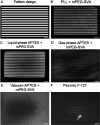
Digital pattern design (A) and patterning outcomes of PDMS passivated with (B) PLL + mPEG-SVA, (C) liquid-phase APTES + mPEG-SVA, (D) gas-phase APTES + mPEG-SVA, (E) vacuum APTES + mPEG-SVA, and (F) Pluronic F-127. After patterning, rhodamine-labeled FN is incubated (50 μg/mL, 5 min) and visualized using fluorescence microscopy. Scale bar: 50 μm.
Figure 3
Figure 3
(A) Intensity profiles of four lines (10 μm width, 10 μm gap size) of rhodamine-labeled FN (50 μg/mL, 5 min) using microcontact printing and the LIMAP approach on PDMS and glass substrates. (B) hBMSCs on microcontact-printed rhodamine-labeled FN lines (a 10 μm width, a 10 μm gap size) on glass surfaces. The merged image shows the F-actin cytoskeleton (green), nuclei (blue), and FN (red). hBMSCs show a contact-guidance-dominated response by aligning in the direction of the patterned lines. Scale bar: 50 μm. (C) hBMSCs on rhodamine-labeled FN lines (a 10 μm width, a 10 μm gap size) patterned on a convex cylindrical structure with κ = 1/500 μm–1. The merged image shows the F-actin cytoskeleton (green), nuclei (blue), and FN (red). Scale bar: 50 μm.
Figure 4
Figure 4
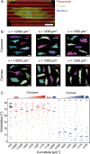
(A) hmFB on a flat, patterned PDMS substrate with FN lines (red, 10 μm lines and a 10 μm gap size) stained for the actin cytoskeleton (green) and nucleus (blue). Scale bar: 50 μm. (B) Example outlines of single hmFBs on patterned curvatures used for quantification of the orientation response. The direction of the contact-guidance cues and curvature is indicated with red bars. Scale bar: 50 μm. (C) Orientation response of hmFBs on both flat and structured PDMS (concave and convex cylinders with curvatures ranging from κ = 1/2500 to 1/125 μm–1, with the degree of curvature schematically indicated on top, n = 11–42 cells). Individual cells are represented by dots and the median by a line. For concave features (red), a similar orientation response on the complete range of curvatures is observed compared to hmFBs on flat substrates (black). In the case of convex features (blue), a transition in the orientation behavior can be noted with increasing curvature. hmFBs tend to align in the direction of the contact-guidance pattern and curvature (90°) if κ = 1/2500 μm–1, whereas the curvature-guidance cue is dominant for curvatures of κ > 1/2500 μm–1 (0°). Asterisks indicate statistical differences compared to the orientation on flat substrates (*p < 0.05).
Figure 5
Figure 5
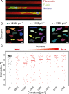
(A) HUVECs on flat, patterned PDMS substrates with FN lines (red, 20 μm lines and a 20 μm gap size) stained for the actin cytoskeleton (green) and nuclei (blue). Scale bar: 50 μm. (B) Example outlines of single HUVECs on patterned concave curvatures used for quantification of the orientation response. The direction of the contact-guidance cues and curvature is indicated with red bars. Scale bar: 50 μm. (C) Orientation response of HUVECs on both flat and concave PDMS (curvatures ranging from κ = 1/2500 to 1/125 μm–1, with the degree of curvature schematically indicated on top, n = 29–91 cells). Individual cells are represented by dots and the median by a line. Overall, a similar orientation response on the complete range of curvatures (red) is observed compared to HUVECs on flat substrates (black). Asterisks indicate statistical differences compared to the orientation on flat substrates (*p < 0.05).

References

    1. Frantz C.; Stewart K. M.; Weaver V. M. The Extracellular Matrix at a Glance. J. Cell Sci. 2010, 123, 4195–4200. 10.1242/jcs.023820. - DOI - PMC - PubMed
    1. MacQueen L.; Sun Y.; Simmons C. A. Mesenchymal Stem Cell Mechanobiology and Emerging Experimental Platforms. J. R. Soc., Interface 2013, 10, 20130179.10.1098/rsif.2013.0179. - DOI - PMC - PubMed
    1. Eyckmans J.; Boudou T.; Yu X.; Chen C. S. A Hitchhiker’s Guide to Mechanobiology. Dev. Cell 2011, 21, 35–47. 10.1016/j.devcel.2011.06.015. - DOI - PMC - PubMed
    1. Jaalouk D. E.; Lammerding J. Mechanotransduction Gone Awry. Nat. Rev. Mol. Cell Biol. 2009, 10, 63–73. 10.1038/nrm2597. - DOI - PMC - PubMed
    1. Teixeira A. I.; Abrams G. A.; Bertics P. J.; Murphy C. J.; Nealey P. F. Epithelial Contact Guidance on Well-Defined Micro- and Nanostructured Substrates. J. Cell Sci. 2003, 116, 1881–1892. 10.1242/jcs.00383. - DOI - PMC - PubMed