

Pt and CoB trilayer Josephson [Formula: see text] junctions with perpendicular magnetic anisotropy
- PMID: 34045523
- PMCID: PMC8159980
- DOI: 10.1038/s41598-021-90432-y
Pt and CoB trilayer Josephson [Formula: see text] junctions with perpendicular magnetic anisotropy
Abstract
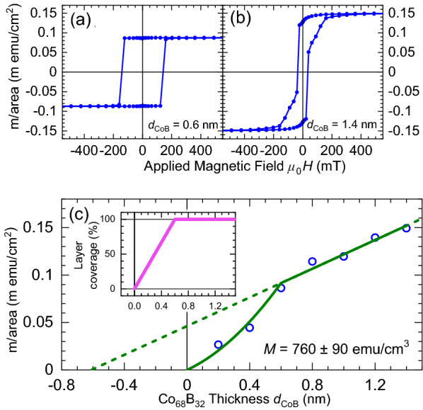
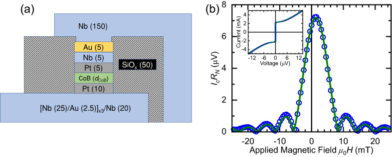
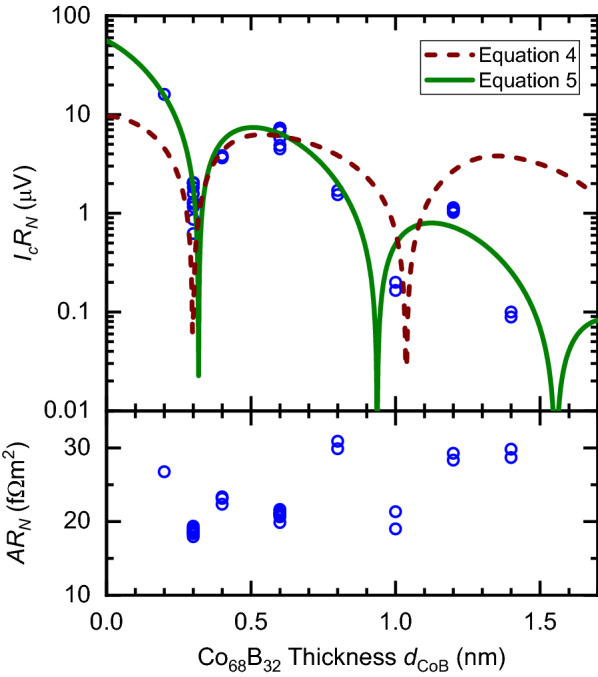
We report on the electrical transport properties of Nb based Josephson junctions with Pt/Co[Formula: see text]B[Formula: see text]/Pt ferromagnetic barriers. The barriers exhibit perpendicular magnetic anisotropy, which has the main advantage for potential applications over magnetisation in-plane systems of not affecting the Fraunhofer response of the junction. In addition, we report that there is no magnetic dead layer at the Pt/Co[Formula: see text]B[Formula: see text] interfaces, allowing us to study barriers with ultra-thin Co[Formula: see text]B[Formula: see text]. In the junctions, we observe that the magnitude of the critical current oscillates with increasing thickness of the Co[Formula: see text]B[Formula: see text] strong ferromagnetic alloy layer. The oscillations are attributed to the ground state phase difference across the junctions being modified from zero to [Formula: see text]. The multiple oscillations in the thickness range [Formula: see text] nm suggests that we have access to the first zero-[Formula: see text] and [Formula: see text]-zero phase transitions. Our results fuel the development of low-temperature memory devices based on ferromagnetic Josephson junctions.
Conflict of interest statement
The authors declare no competing interests.
Figures
Similar articles
-
Thin film epitaxial [111] Co[Formula: see text]Pt[Formula: see text]: structure, magnetisation, and spin polarisation.Sci Rep. 2023 Aug 1;13(1):12468. doi: 10.1038/s41598-023-37825-3. Sci Rep. 2023. PMID: 37528131 Free PMC article.
-
Quantum vortex melting and superconductor insulator transition in a 2D Josephson junction array in a perpendicular magnetic field via diffusion Monte Carlo.J Phys Condens Matter. 2018 Sep 26;30(38):385901. doi: 10.1088/1361-648X/aadafb. Epub 2018 Aug 17. J Phys Condens Matter. 2018. PMID: 30117436
-
Soliton defects and topological [Formula: see text]-periodic superconductivity from an orbital magnetic field effect in edge Josephson junctions.J Phys Condens Matter. 2019 May 1;31(17):175301. doi: 10.1088/1361-648X/ab03b4. Epub 2019 Jan 31. J Phys Condens Matter. 2019. PMID: 30703757
-
Critical switching current density of magnetic tunnel junction with shape perpendicular magnetic anisotropy through the combination of spin-transfer and spin-orbit torques.Sci Rep. 2021 Nov 24;11(1):22842. doi: 10.1038/s41598-021-02185-3. Sci Rep. 2021. PMID: 34819554 Free PMC article.
-
Magnetism in quasi-two-dimensional tri-layer La2.1Sr1.9Mn3O10 manganite.Sci Rep. 2021 Jul 8;11(1):14117. doi: 10.1038/s41598-021-93290-w. Sci Rep. 2021. PMID: 34238952 Free PMC article.
Cited by
-
Superconductivity assisted change of the perpendicular magnetic anisotropy in V/MgO/Fe junctions.Sci Rep. 2021 Sep 24;11(1):19041. doi: 10.1038/s41598-021-98079-5. Sci Rep. 2021. PMID: 34561472 Free PMC article.
-
Thin film epitaxial [111] Co[Formula: see text]Pt[Formula: see text]: structure, magnetisation, and spin polarisation.Sci Rep. 2023 Aug 1;13(1):12468. doi: 10.1038/s41598-023-37825-3. Sci Rep. 2023. PMID: 37528131 Free PMC article.
-
Upper critical fields in normal metal-superconductor-normal metal trilayers.Sci Rep. 2025 Apr 16;15(1):13076. doi: 10.1038/s41598-025-98332-1. Sci Rep. 2025. PMID: 40240512 Free PMC article.
References
Grants and funding
LinkOut - more resources
Full Text Sources
Other Literature Sources
