. 2021 Jul;8(14):e2100916.
doi: 10.1002/advs.202100916. Epub 2021 May 29.

Spider-Inspired Electrohydraulic Actuators for Fast, Soft-Actuated Joints

Affiliations

Spider-Inspired Electrohydraulic Actuators for Fast, Soft-Actuated Joints

Nicholas Kellaris et al. Adv Sci (Weinh). 2021 Jul.

Abstract

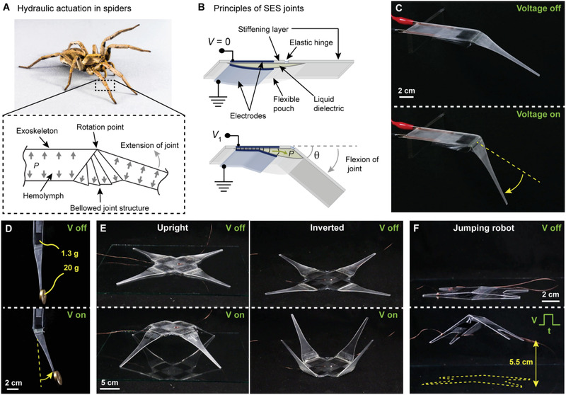
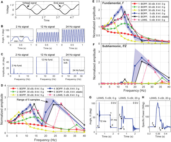
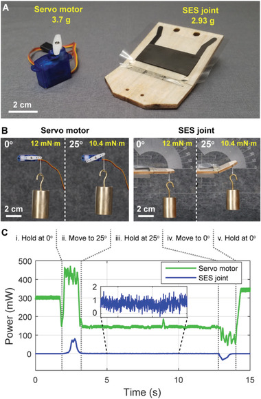
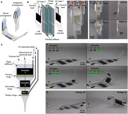
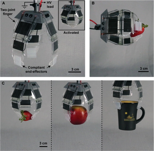
The impressive locomotion and manipulation capabilities of spiders have led to a host of bioinspired robotic designs aiming to reproduce their functionalities; however, current actuation mechanisms are deficient in either speed, force output, displacement, or efficiency. Here-using inspiration from the hydraulic mechanism used in spider legs-soft-actuated joints are developed that use electrostatic forces to locally pressurize a hydraulic fluid, and cause flexion of a segmented structure. The result is a lightweight, low-profile articulating mechanism capable of fast operation, high forces, and large displacement; these devices are termed spider-inspired electrohydraulic soft-actuated (SES) joints. SES joints with rotation angles up to 70°, blocked torques up to 70 mN m, and specific torques up to 21 N m kg-1 are demonstrated. SES joints demonstrate high speed operation, with measured roll-off frequencies up to 24 Hz and specific power as high as 230 W kg-1 -similar to human muscle. The versatility of these devices is illustrated by combining SES joints to create a bidirectional joint, an artificial limb with independently addressable joints, and a compliant gripper. The lightweight, low-profile design, and high performance of these devices, makes them well-suited toward the development of articulating robotic systems that can rapidly maneuver.

Keywords: HASEL; SES; actuator; articulation; bioinspired; electrohydraulic; soft.


Conflict of interest statement

The authors declare no conflict of interest.

Figures

Figure 1
Figure 1
Principles of spider‐inspired electrohydraulic soft‐actuated (SES) joints. A) Hydraulic operation of the tibia‐metatarsus joint of a spider. Pressurization of hemolymph fluid causes the leg to extend. Adapted with permission.[ 51 ] Copyright 2014, IEEE. A wolf spider (family Lycosidae) is pictured. B) SES joints consist of a flexible pouch filled with liquid dielectric, and a pair of opposing electrodes on the outside. A stiffening layer is placed on one side to constrain actuation while a flexible hinge provides stability and a passive restoring force. On application of voltage, Maxwell stress causes the electrodes to zip together progressively, which pressurizes the liquid dielectric (P) and causes flexion of the joint to angle θ. C) SES joint with voltage off and with voltage on (8 kV applied), which causes flexion of the joint. D) The rigid stiffening layer supports efficient force transfer along the limb; here, a 1.3 g actuator is lifting 20 g almost 10 cm away from the point of rotation. E) Multiple SES joints can be combined to create different types of robotic structures. F) SES joints feature excellent power‐to‐weight ratio and can be used to create jumping robots.
Figure 2
Figure 2
Fabrication process for SES joints. A) Representative fabrication steps for the material systems used in this paper. 1) Two layers of polymer film are heat sealed together to define a pouch shape, leaving a small opening at the bottom for filling. 2) Carbon electrodes are screen printed on either side of the pouch; excess film is trimmed from the sides, leaving a skirt on the sides and bottom to prevent electrical arcing around the actuator during operation. 3) The flexible joint is made from a flexible hinge layer bonded to a two‐piece stiffening layer with much higher mechanical stiffness. An adhesive layer is applied over the transparency to connect the actuator to the joint. 4) The pouch is bonded to the flexible joint and filled with liquid dielectric using a syringe with an angled needle inserted into the filling port. The filling port is then closed by heat sealing. B) The completed SES joint is characterized by the electrode height (h), the pouch width (w), and the height of the notched region that is not covered by electrodes (r). Joints have a natural resting angle, θ 0.
Figure 3
Figure 3
Evaluation of quasi‐static actuation performance in SES joints. A) Torque versus angle curves at 9 kV for SES joints with varying pouch geometry (h × w × r) and film material. For the same voltage, using L0WS increased torque output by ≈ 50% (compared to BOPP). B) Angle versus voltage curves for joints with varying hinge thickness (corresponding to hinge stiffness). Less stiff hinges reached higher angles at a given voltage. C) Angle versus voltage curves for joints made from BOPP films with zero‐ and 10 g external loads (3.5 cm away from the hinge). Hinges were tested horizontally, with the direction of the gravitational force denoted by F g.
Figure 4
Figure 4
Quasi‐static model of the SES joint. A) Undeformed state: an empty shell (length L, width w out of the plane of the figure) that is covered on both sides with electrodes (length L E, width w out of the plane of the figure) is bonded to a stiffening layer (assumed to be rigid); a portion (length L 1) attaches to the stationary side, and the remaining portion (length L 2) attaches to the rotating side (length L 3). B) Filled state: when filled with an incompressible liquid dielectric, the cross‐sectional area of the shell (thickness t, relative permittivity ε r) increases to A and the hinge (spring constant k b) rotates by an angle θ 0. Elastic strains in the shell and the joint between shell and stiffening layer (assumed to be rigid) are modeled as an elongation ΔL 0 of the top film of the shell (spring constant k l). C) When a voltage Φ is applied between the electrodes, they zip together by a length z and the hinge rotates to an angle θ. The top film elongates by ΔL. The unzipped portion of the top film is modeled as a cylinder section of length l with central angle 2α and chord length c. Note that A remains constant. We modeled two cases: either a torque T or a vertical load mg acts on the end of the hinge. D,E) Comparison of model predictions with experimental results.
Figure 5
Figure 5
Evaluation of dynamic actuation performance in SES joints. A) The voltage signal used for testing frequency response was a modified sine wave with amplitude V. B) Angle versus time responses of a 2 × 4 × 1 BOPP actuator with 5 cSt fluid at 8 kV. Note that the angular response to the 24 Hz signal only had 12 maxima and minima in 1 s. C) The discrete Fourier transforms (DFTs) of the time domain responses in (B) showed a substantial subharmonic resonance when driven by a 24 Hz signal (corresponding to 12 Hz response) due to the nonlinearity of SES joints. D) Frequency response of actuators when analyzed using periodically occurring minimum and maximum values in the time domain (B) to determine amplitude, plotted against the frequency of the driving voltage signal. Various combinations of pouch materials, liquid dielectrics, voltages, and loads were tested. Test 5 added an additional elastic restoring force (Figure S7, Supporting Information). For test 4, the plotted line corresponds to the mean values from five tested samples, while the shaded region is bounded by lowest and highest measured values for those samples. E) Amplitude of the fundamental response (C) plotted against the frequency of the driving voltage signal. F) Amplitude of the subharmonic response (C) plotted against the frequency of the driving voltage signal. G) Response of a 2 × 4 × 1 L0WS joint with 5 cSt fluid to a step voltage at 9 kV, with no load (left) and a 20 g load (right), and H) the corresponding specific power output for a 20 g load.
Figure 6
Figure 6
Comparison of power consumption of a servo motor and an SES joint. A) A lightweight SES joint made from balsa wood (2.93 g, peak torque ≈ 30 mN m−1 at 9 kV) produced similar maximum torque as a lightweight servo motor (3.7 g without wires, peak torque ≈ 40 mN m at 5 V). B) The weight and lever arm were chosen such that the servo motor and SES joint applied the same torque at all angles. C) Power consumption of both actuators throughout an identical series of motions. The servo motor consumed 140 mW while holding the load at 25° (step iii, (B)), while the SES joint consumed <1 mW.
Figure 7
Figure 7
Combining multiple SES joints for different types of motion. A) Combining SES joints into different arrangements enables more diverse actuation: antagonist arrangements allow bidirectional actuation while series arrangements increase angular output. B) A bidirectional SES joint was created by placing one actuator on either side of a bidirectional hinge using transfer tape (not shown). The hinge was made from flexible stiffeners attached to a two‐side adhesive transparency. A gap in the stiffeners allowed for bidirectional actuation in the hinge. C) A bidirectional SES joint made from two 2 × 4 × 1 cm BOPP actuators. Each actuator was independently controlled using V 1 and V 2. D) Activating the left (top) and right (bottom) actuators separately using a voltage of 8 kV resulted in hinge angles of 18° and 20°, respectively. E) By placing several SES joints in series, the overall flexion angle was increased, creating an artificial limb with independently addressable joints. F) Three SES joints activated sequentially with voltages of 8 kV. G) When the actuators were facing downward, the limb could lift itself off the ground.
Figure 8
Figure 8
A three‐finger gripper based on series arrangements of SES joints. A) The gripper used three fingers with two joints each. These fingers were actuated simultaneously to perform gripping tasks. Compliant pads coated with a silicone elastomer increased contact area and friction. The gripper closed entirely under application of an 8 kV DC voltage (inset). B) SES joints had sufficient mechanical stability to enable horizontal gripping of lightweight objects such as a strawberry. A voltage of 6 kV was used. C) The compliance of each finger enabled the gripper to grasp a variety of objects without the need for feedback, including a delicate strawberry (18 g), an apple (170 g), and a ceramic mug (270 g). A voltage of 8 kV was used for all three objects.

References

    1. Yuk H., Lin S., Ma C., Takaffoli M., Fang N. X., Zhao X., Nat. Commun. 2017, 8, 14230. - PMC - PubMed
    1. Kumar K., Liu J., Christianson C., Ali M., Tolley M. T., Aizenberg J., Ingber D. E., Weaver J. C., Bertoldi K., Soft Rob. 2017, 4, 317. - PubMed
    1. Tolley M. T., Shepherd R. F., Mosadegh B., Galloway K. C., Wehner M., Karpelson M., Wood R. J., Whitesides G. M., Soft Rob. 2014, 1, 213.
    1. Suzumori K., Iikura S., Tanaka H., 1991 IEEE Int. Conf. on Robotics and Automation Proc., IEEE, Piscataway, NJ: 1991, Vol. 2, pp. 1622–1627.
    1. Polygerinos P., Wang Z., Galloway K. C., Wood R. J., Walsh C. J., Rob. Auton. Syst. 2015, 73, 135.

Publication types

LinkOut - more resources