. 2021 May;8(3):035501.
doi: 10.1117/1.JMI.8.3.035501. Epub 2021 May 24.

Accuracy of commercial intraoral scanners

Affiliations

Accuracy of commercial intraoral scanners

Mattia Sacher et al. J Med Imaging (Bellingham). 2021 May.

Abstract

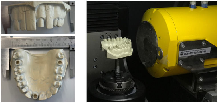
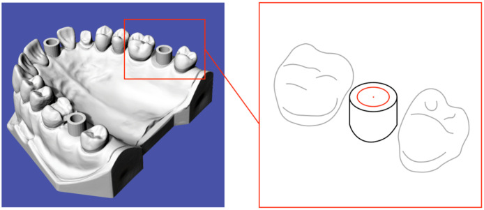
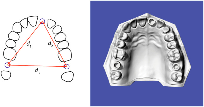
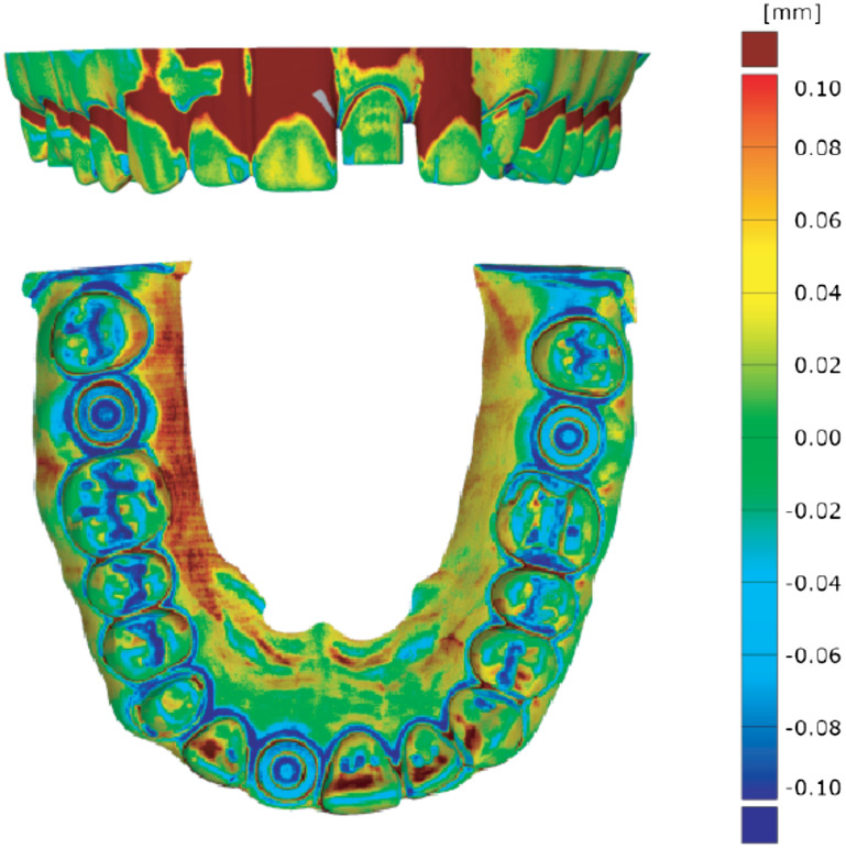
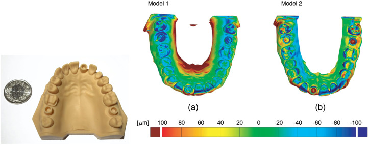
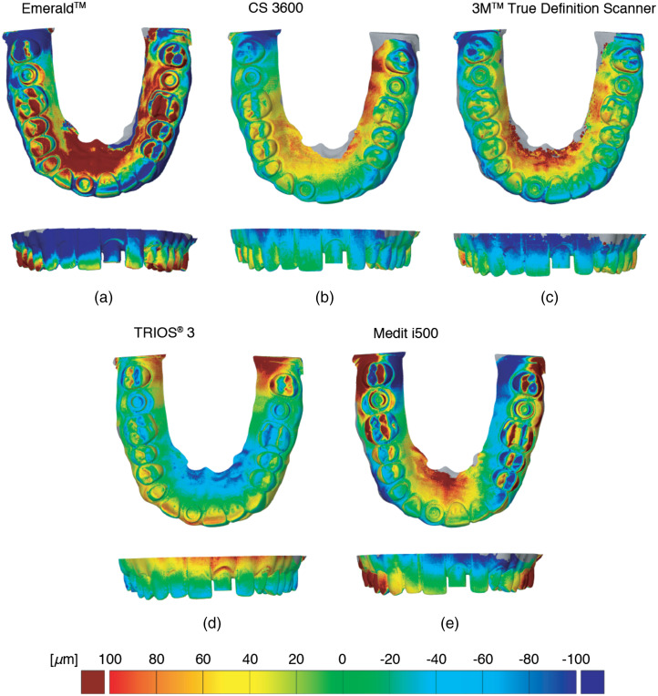
Purpose: In dental offices, there is a trend replacing conventional silicone impressions and plaster cast models by imaging data of intraoral scanners to map the denture and surrounding tissues. The aim of the study is the analysis of the accuracy of selected commercially available scanners. The accuracy is considered as the main drawback in comparison to the conventional approach. Approach: We evaluated the reproduction performance of five optical scanners by a direct comparison with high-resolution hard x-ray computed tomography data, all obtained from a polyetheretherketone model with similarity to a full-arch upper jaw. Results: Using the software GOM Inspect (GOM GmbH, Braunschweig, Germany), we could classify the intraoral scanners into two groups. The more accurate instruments gave rise to the following precision values: 35 μ m (TRIOS® 3, 3shape, Copenhagen, Denmark), 43 μ m (CS 3600, Carestream, Atlanta, Georgia), and 46 μ m (3M™ True Definition Scanner, 3M ESPE, St. Paul, Minnesota). The less precise systems yielded 93 μ m (Medit i500, Medit corp., Seongbuk-gu, South Korea) and 97 μ m (Emerald™, Planmeca Oy, Helsinki, Finland). Conclusions: The selected scanners are suitable for single crowns, small bridges, and separate quadrants prostheses. Scanners based on triangulation are hardly appropriate for full-arch prostheses. Besides precision, however, the choice of the scanner depends on scanning time, intraoral-camera size, and the user's learning curve. The developed protocol, which includes three-dimensional (3D) imaging and advanced computational tools for the registration with the design data, will be increasingly used in geometrical metrology by nondestructive procedures to perform dimensional measurements with micrometer precision and is capable for detailed 3D geometrical models reconstruction.

Keywords: deviation field; full-arch scanning; micro computed tomography; registration; stereolithography printer; three-dimensional accuracy evaluation.


Figures

Fig. 1
Fig. 1
The PEEK model’s size corresponds to that found in the human body, as displayed by the photographs on the left. Three well-defined hollow cylinders were incorporated to determine the precision of the IOSs. The other photograph shows the placement of the model on the rotation stage in the CT-system nanotom® m (phoenix|x-ray, GE Sensing & Inspection Technologies GmbH, Wunstorf, Germany).
Fig. 2
Fig. 2
Scheme for determining the center points of the hollow cylinders via the Gaussian best-fit method.
Fig. 3
Fig. 3
Scheme for specifying the three distances. Distance d1 characterizes the length between 17 and 21, distance d2 is the length between 21 and 27, and distance d3 corresponds to the length between 17 and 27.
Fig. 4
Fig. 4
3D representation of the differences between the desired geometry, given by the STL-file and the data from scan 4 and according to the color bar and the related values on the right. Perfect agreement is represented by the green color. Obviously, the milling tool provided a reasonable result, although in some areas more material than desired was removed (blue color), while other areas show excess material (red color). One can further observe that the hollow cylinders are larger in size than planned, but because we only consider the center points, the determination of distances is hardly affected.
Fig. 5
Fig. 5
3D representation of the differences between the desired geometry, given by the STL-file, we used for the model preparation (photograph on the left) and the high-resolution tomography data of the two 3D-printed models. The green color shows parts without differences, whereas the red and blue colors indicate excess and deficiency of material, respectively.
Fig. 6
Fig. 6
Color-coded deviation field of the IOS derived from the difference to the selected ground truth, i.e., the high-resolution tomography experiments using nanotom® m. The green color shows agreement, whereas the red and blue colors point the locations of positive and negative deviations.

References

    1. Ender A., Attin T., Mehl A., “In vivo precision of conventional and digital methods of obtaining complete-arch dental impressions,” J. Prosthet. Dent. 115(3), 313–320 (2016).JPDEAT10.1016/j.prosdent.2015.09.011 - DOI - PubMed
    1. Vögtlin C., et al. , “Comparing the accuracy of master models based on digital intra-oral scanners with conventional plaster casts,” Phys. Med. 1, 20–26 (2016).10.1016/j.phmed.2016.04.002 - DOI
    1. Brown G. B., et al. , “Accuracy of 3-dimensional printed dental models reconstructed from digital intraoral impressions,” Am. J. Orthod. Dentofacial Orthop. 154(5), 733–739 (2018).AJOOEB10.1016/j.ajodo.2018.06.009 - DOI - PubMed
    1. Seelbach P., Brueckel C., Wostmann B., “Accuracy of digital and conventional impression techniques and workflow,” Clin. Oral Investig. 17(7), 1759–1764 (2013).10.1007/s00784-012-0864-4 - DOI - PubMed
    1. Lim J. H., et al. , “Comparison of digital intraoral scanner reproducibility and image trueness considering repetitive experience,” J. Prosthet. Dent. 119(2), 225–232 (2018).JPDEAT10.1016/j.prosdent.2017.05.002 - DOI - PubMed