

Rotation Active Sensors Based on Ultrafast Fibre Lasers
- PMID: 34069464
- PMCID: PMC8159120
- DOI: 10.3390/s21103530
Rotation Active Sensors Based on Ultrafast Fibre Lasers
Abstract
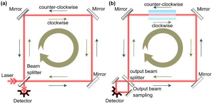
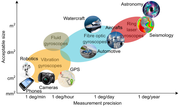
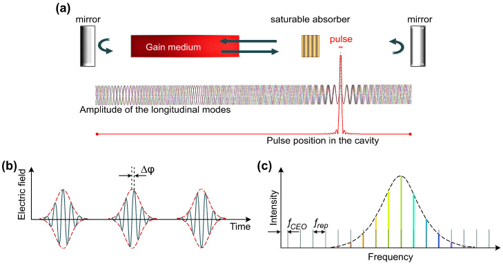
Gyroscopes merit an undeniable role in inertial navigation systems, geodesy and seismology. By employing the optical Sagnac effect, ring laser gyroscopes provide exceptionally accurate measurements of even ultraslow angular velocity with a resolution up to 10-11 rad/s. With the recent advancement of ultrafast fibre lasers and, particularly, enabling effective bidirectional generation, their applications have been expanded to the areas of dual-comb spectroscopy and gyroscopy. Exceptional compactness, maintenance-free operation and rather low cost make ultrafast fibre lasers attractive for sensing applications. Remarkably, laser gyroscope operation in the ultrashort pulse generation regime presents a promising approach for eliminating sensing limitations caused by the synchronisation of counter-propagating channels, the most critical of which is frequency lock-in. In this work, we overview the fundamentals of gyroscopic sensing and ultrafast fibre lasers to bridge the gap between tools development and their real-world applications. This article provides a historical outline, highlights the most recent advancements and discusses perspectives for the expanding field of ultrafast fibre laser gyroscopes. We acknowledge the bottlenecks and deficiencies of the presented ultrafast laser gyroscope concepts due to intrinsic physical effects or currently available measurement methodology. Finally, the current work outlines solutions for further ultrafast laser technology development to translate to future commercial gyroscopes.
Keywords: Dispersive Fourier Transform; fibre gyroscope; fibre sensors; mode-locked laser.
Conflict of interest statement
The authors declare no conflict of interest.
Figures
Similar articles
-
Bidirectional dark-soliton fiber lasers for high-sensitivity gyroscopic application.Opt Lett. 2019 Aug 15;44(16):4008-4011. doi: 10.1364/OL.44.004008. Opt Lett. 2019. PMID: 31415534
-
Isolator-free switchable uni- and bidirectional hybrid mode-locked erbium-doped fiber laser.Opt Express. 2016 Jul 11;24(14):15721-9. doi: 10.1364/OE.24.015721. Opt Express. 2016. PMID: 27410844
-
Mode-Locked Fiber Laser Sensors with Orthogonally Polarized Pulses Circulating in the Cavity.Sensors (Basel). 2023 Feb 24;23(5):2531. doi: 10.3390/s23052531. Sensors (Basel). 2023. PMID: 36904737 Free PMC article.
-
Temporal and spatiotemporal soliton molecules in ultrafast fibre lasers.Nanophotonics. 2025 Feb 5;14(6):677-706. doi: 10.1515/nanoph-2024-0590. eCollection 2025 Apr. Nanophotonics. 2025. PMID: 40182798 Free PMC article. Review.
-
Review of the Usefulness of Various Rotational Seismometers with Laboratory Results of Fibre-Optic Ones Tested for Engineering Applications.Sensors (Basel). 2016 Dec 16;16(12):2161. doi: 10.3390/s16122161. Sensors (Basel). 2016. PMID: 27999299 Free PMC article. Review.
Cited by
-
A Quantum Ring Laser Gyroscope Based on Coherence de Broglie Waves.Sensors (Basel). 2022 Nov 10;22(22):8687. doi: 10.3390/s22228687. Sensors (Basel). 2022. PMID: 36433284 Free PMC article.
References
-
- Scarborough J.B. The Gyroscope. Interscience Publishers; London, UK: 1958.
-
- Johnson W.R. Description of an Apparatus called the Rotascope, for exhibiting several phenomena and illustrating certain laws of rotary motion. Am. J. Sci. Arts (1820–1879) 1832;21:264B.
-
- Macek W.M., Davis D.T.M. Rotation rate sensing with traveling-wave ring lasers. Appl. Phys. Lett. 1963;2:67–68. doi: 10.1063/1.1753778. - DOI
-
- Sagnac G. L’ether lumineux demontre par l’effet du vent relatif d’ether dans un interferometre en rotation uniforme. Comptes Rendus. 1913;157:708–710.
Publication types
LinkOut - more resources
Full Text Sources
Other Literature Sources
Miscellaneous
