. 2021 May 30;21(11):3798.
doi: 10.3390/s21113798.

Effect of Different Head Hole Position on the Rotational Resistance and Stability of Orthodontic Miniscrews: A Three-Dimensional Finite Element Study

Affiliations

Effect of Different Head Hole Position on the Rotational Resistance and Stability of Orthodontic Miniscrews: A Three-Dimensional Finite Element Study

Jin-Young Choi et al. Sensors (Basel). .

Abstract

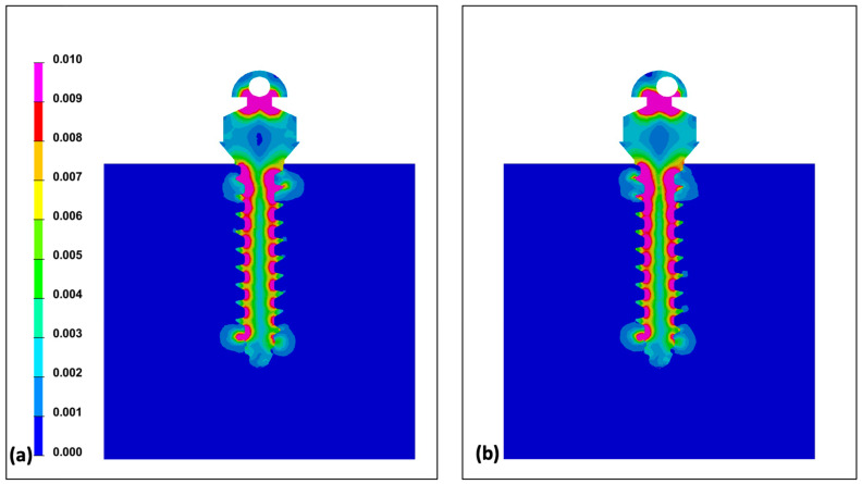
The orthodontic miniscrew is driven into bone in a clockwise direction. Counter-clockwise rotational force applied to the implanted miniscrew can degrade the stability. The purpose of this three-dimensional finite element study was to figure out the effect of shifting the miniscrew head hole position from the long axis. Two miniscrew models were developed, one with the head hole at the long axis and the other with an eccentric hole position. One degree of counter-clockwise rotation was applied to both groups, and the maximum Von-Mises stress and moment was measured under various wire insertion angles from -60° to +60°. All Von-Mises stress and moments increased with an increase in rotational angle or wire insertion angle. The increasing slope of moment in the eccentric hole group was significantly higher than that in the centric hole group. Although the maximum Von-Mises stress was higher in the eccentric hole group, the distribution of stress was not very different from the centric hole group. As the positive wire insertion angles generated a higher moment under a counter-clockwise rotational force, it is recommended to place the head hole considering the implanting direction of the miniscrew. Clinically, multidirectional and higher forces can be applied to the miniscrew with an eccentric head hole position.

Keywords: implantation angle; miniscrew head hole; wire insertion angle.


Conflict of interest statement

The authors declare no conflict of interest.

Figures

Figure 1
Figure 1
Two types of miniscrews based on the position of a hole in the head part: (a) the left one has a hole in the middle of the miniscrew’s head part (centric hole group), and the right one has a hole out of center of the miniscrew’s head part (eccentric hole group); (b) in the constructed model for this study, the two types of miniscrews were assumed to be placed totally into the alveolar bone. Thickness of the cortical bone was modeled at 1.2 mm, and the trabecular bone was thick enough to accept the whole length of the miniscrews. The left model is a miniscrew of the centric hole group and the right one is a miniscrew of the eccentric hole group.
Figure 2
Figure 2
Direction of rotation applied to the miniscrew model: (a) on the top view of the miniscrew head part in the centric hole group, counterclockwise rotation was applied with the long axis of the miniscrew as a center of rotation; (b) same rotational direction (counterclockwise rotation) was applied to a miniscrew in the eccentric hole group.
Figure 3
Figure 3
Miniscrews were assumed to be placed with various angulations on the alveolar bone surface. An archwire parallel to the alveolar bone and the occlusal plane passing through the hole of the angulated miniscrew forms corresponding angles with the long axis of the miniscrew. To make the same condition among the models, whole screw part was placed into the alveolar bone and the archwire was inserted with angles from −60° to +60° with an angle interval of 15°.
Figure 4
Figure 4
Distribution of Von-Mises stress under the condition of 1° counter-clockwise rotation of the miniscrew: (a) centric hole group; (b) eccentric hole group. Both groups showed relatively even distribution of Von-Mises stress.
Figure 5
Figure 5
Distribution of Von-Mises stress under the condition of 1° counter-clockwise rotation of the miniscrew placed with various positive angles on the alveolar bone surface: (a) Von-Mises stress distribution of the miniscrew at +15° angulation in centric and eccentric hole groups; (b) Von-Mises stress distribution of the miniscrew at +30° angulation in centric and eccentric hole groups; (c) Von-Mises stress distribution of the miniscrew at +45° angulation in centric and eccentric hole groups; (d) Von-Mises stress distribution of the miniscrew at +60° angulation in centric and eccentric hole groups. In both groups, more stress was concentrated on the upper 1/3 as the angle increased.
Figure 6
Figure 6
Distribution of maximum Von-Mises stress under the condition of 1° counter-clockwise rotation of the miniscrew placed with various negative angles on the alveolar bone surface: (a) Von-Mises stress distribution of the miniscrew at −15° angulation in centric and eccentric hole groups; (b) Von-Mises stress distribution of the miniscrew at −30° angulation in centric and eccentric hole groups; (c) Von-Mises stress distribution of the miniscrew at −45° angulation in centric and eccentric hole groups; (d) Von-Mises stress distribution of the miniscrew at −60° angulation in centric and eccentric hole groups. In both groups, more stress was concentrated on the upper 1/3 as the angle increased, and the stress distribution tendency was opposite to the result of the miniscrews implanted at positive angles.
Figure 7
Figure 7
Von-Mises stress under 1° of counter-clockwise rotation at the alveolar bone and miniscrew at various angles: (a) Von-mises stress at the alveolar bone showing the higher stress in the centric hole group; (b) Von-Mises stress at the whole miniscrew showing the higher stress in the centric hole group and at positive angles.
Figure 8
Figure 8
Maximum Von-Mises stress under 1° of counter-clockwise rotation at each part of the miniscrew: (a) Von-Mises stress at the upper 1/3 of the miniscrew showing relatively high value in the eccentric hole group and in the negative angles; (b) Von-Mises stress at the middle 1/3 of the miniscrew; (c) Von-Mises stress at the apical 1/3 of the miniscrew.
Figure 9
Figure 9
Moment required to unwind the miniscrew for 1° in counter-clockwise direction in centrical and eccentric hole groups: (a) overall moment in the centric hole group; (b) overall moment in the eccentric hole group; (c) moment at the cortical bone in the centric hole group; (d) moment at the cortical bone in the eccentric hole group; (e) moment at the trabecular bone in the centric hole group; (f) moment at the trabecular bone in the eccentric hole group.
Figure 10
Figure 10
Suggestion of an ideal head hole position for maximum resistance to counter-clockwise rotational force. When the miniscrew tip directed the apical side with an angulation to the alveolar bone surface, the hole positioned on the upper (apical) side of the head would generate the maximum resistance to the rotational force.

Similar articles

References

    1. Chang H.P., Tseng Y.C. Miniscrew implant applications in contemporary orthodontics. Kaohsiung J. Med. Sci. 2014;30:111–115. doi: 10.1016/j.kjms.2013.11.002. - DOI - PMC - PubMed
    1. Mo S.S., Noh M.K., Kim S.H., Chung K.R., Nelson G. Finite element study of controlling factors of anterior intrusion and torque during Temporary Skeletal Anchorage Device (TSAD) dependent en masse retraction without posterior appliances: Biocreative hybrid retractor (CH-retractor) Angle Orthod. 2020;90:255–262. doi: 10.2319/050619-315.1. - DOI - PMC - PubMed
    1. Çifter M., Saraç M. Maxillary posterior intrusion mechanics with mini-implant anchorage evaluated with the finite element method. Am. J. Orthod. Dentofac. Orthop. 2011;140:e233–e241. doi: 10.1016/j.ajodo.2011.06.019. - DOI - PubMed
    1. Park J.H., Saito T., Yoo S.K., Alfaifi M., Kook Y.A. Distalization with a modified C-palatal plate for severe upper crowding and a missing lower incisor. Korean J. Orthod. 2020;50:52–62. doi: 10.4041/kjod.2020.50.1.52. - DOI - PMC - PubMed
    1. Antoszewska-Smith J., Sarul M., Łyczek J., Konopka T., Kawala B. Effectiveness of orthodontic miniscrew implants in anchorage reinforcement during en-masse retraction: A systematic review and meta-analysis. Am. J. Orthod. Dentofac. Orthop. 2017;151:440–455. doi: 10.1016/j.ajodo.2016.08.029. - DOI - PubMed