. 2021 May 31;21(11):3805.
doi: 10.3390/s21113805.

Analytic Design of Segmented Phase Grating for Optical Sensing in High-Precision Alignment System

Affiliations

Analytic Design of Segmented Phase Grating for Optical Sensing in High-Precision Alignment System

Guanghua Yang et al. Sensors (Basel). .

Abstract

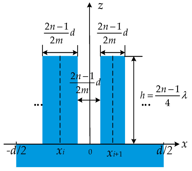
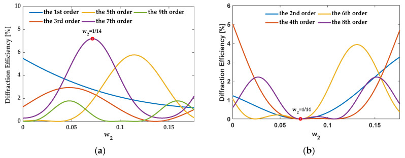
Ultra-precision measurement systems are important for semiconductor manufacturing processes. In a phase grating sensing alignment (PGA) system, the measurement accuracy largely depends on the intensity of the diffraction signal and its signal-to-noise ratio (SNR), both of which are associated with the grating structure. Although an equally segmented grating structure could increase the signal of a high odd order, it could also strengthen the signals at the zeroth and even orders which are the main contributors of stray light. This paper focuses on the practical problem of differently responding diffraction orders but in one grating structure. An analytical relationship has been established between the diffraction efficiency and the segment structure of phase grating. According to this analytic model, we then propose a design method to increase the diffraction signal at high odd orders and, meanwhile, to decrease it at the zeroth and even orders. The proposed method provides a fast and effective way to obtain the globally optimal grating structure in the valid scope. Furthermore, the design examples are also verified by means of numerical simulation tool-rigorous coupled-wave analysis (RCWA) software. As a result, the proposed method gives insight into the diffraction theory of segmented grating and the practical value to greatly improve the design efficiency.

Keywords: alignment system; diffraction efficiency; phase grating.


Conflict of interest statement

The authors declare no conflict of interest.

Figures

Figure 1
Figure 1
(a) The profile of a standard phase grating; (b) a cross-section in one period.
Figure 2
Figure 2
(a) The profile of a segmented phase grating; (b) a cross-section in one period.
Figure 3
Figure 3
Segmented grating structure with the zeroth order eliminated.
Figure 4
Figure 4
Schematic diagram of diffraction field vector superposition of segmented phase grating.
Figure 5
Figure 5
Diffraction efficiency of standard grating as a function of duty cycle and groove depth at diffraction orders from 0 to 9.
Figure 6
Figure 6
Segmented grating structure with the odd order m enhanced.
Figure 7
Figure 7
Grating C is divided into grating A and grating B.
Figure 8
Figure 8
Grating D consists of grating A and grating B shifted along the x-axis with d/2.
Figure 9
Figure 9
Segmented grating structure with even orders eliminated.
Figure 10
Figure 10
Grating structure with even diffraction orders eliminated when n = 3.
Figure 11
Figure 11
Grating structure with even diffraction orders eliminated when n = 5.
Figure 12
Figure 12
(a) The critical points of the groove depth h. (b) The average diffraction efficiency of the zeroth and 5th order as a function of the groove depth for the 5th order enhanced grating with three segmented ridges.
Figure 13
Figure 13
Flow chart of design method of segmented grating.
Figure 14
Figure 14
The structure of AH53_opt and AH53_opt’ in one period.
Figure 15
Figure 15
The diffraction efficiency of orders as a function of w2. (a) The odd orders, (b) the even orders.
Figure 16
Figure 16
The structure of AH53 in one period.
Figure 17
Figure 17
The diffraction efficiency of orders as a function of w2 when {fi} is {3/14, 1/14, 3/14}. (a) The odd orders, (b) the even orders.
Figure 18
Figure 18
The diffraction efficiency of orders as a function of w2 when {fi} is {1/14, 5/14, 1/14}. (a) The odd orders, (b) the even orders.
Figure 19
Figure 19
The diffraction efficiency as a function of w2 when {fi} is {1/14, 1/14, 3/14, 1/14, 1/14}. (a) The odd orders, (b) the even orders.
Figure 20
Figure 20
The structures of AH74 and AH74_opt in one period. (a) AH74, (b) AH74_opt1, (c) AH74_opt2, (d) AH74_opt3.
Figure 21
Figure 21
Diffraction efficiency of AH53. (a) AH53 with the groove depth of 158.25 nm; (b) AH53 with the groove depth of 143 nm.
Figure 22
Figure 22
Diffraction efficiency of AH53_opt. (a) AH53_opt with the groove depth of 158.25 nm; (b) AH53_opt with the groove depth of 143 nm.
Figure 23
Figure 23
Diffraction efficiency of AH74. (a) AH74 with the groove depth of 158.25 nm; (b) AH74 with the groove depth of 143 nm.
Figure 24
Figure 24
Diffraction efficiency of AH74_opt3. (a) AH74_opt3 with the groove depth of 158.25 nm; (b) AH74_opt3 with the groove depth of 143 nm.
Figure 25
Figure 25
Optimized AH53. (a) Initial structure; (b) objective functions.
Figure 26
Figure 26
The diffraction efficiency after 13,000 iterations. (a) The 5th order; (b) the 4th order.
Figure 27
Figure 27
Optimized AH53. (a) Initial structure; (b) objective functions.
Figure 28
Figure 28
The diffraction efficiency after 150 iterations. (a) The 5th order; (b) the 4th order.

References

    1. Orji N.G., Badaroglu M., Barnes B.M., Beitia C., Bunday B.D., Celano U., Kline R.J., Neisser M., Obeng Y., Vladar A.E. Metrology for the next generation of semiconductor devices. Nat. Electron. 2018;1:532–547. doi: 10.1038/s41928-018-0150-9. - DOI - PMC - PubMed
    1. Felix N.M., Gabor A.H., Menon V.C., Longo P.P., Halle S.D., Koay C., Colburn M.E. Overlay improvement roadmap: Strategies for scanner control and product disposition for 5 nm overlay; Proceedings of the Metrology, Inspection, and Process Control for Microlithography XXXII; San Jose, CA, USA. 22 March 2018; - DOI
    1. Bunday B.D., Bello A., Solecky E., Vaid A. 7/5 nm logic manufacturing capabilities and requirements of metrology; Proceedings of the Metrology, Inspection, and Process Control for Microlithography XXXII; San Jose, CA, USA. 22 March 2018; - DOI
    1. Oyama K., Yamauchi S., Hara A., Natori S., Yamato M., Okabe N., Koike K., Yaegashi H. Sustainability and applicability of spacerrelated patterning towards 7 nm node; Proceedings of the Advances in Patterning Materials and Processes XXXII; San Jose, CA, USA. 20 March 2015; - DOI
    1. Boef A.J.D. Optical wafer metrology sensors for process-robust CD and overlay control in semiconductor device manufacturing. Surf. Topogr. Metrol. Prop. 2016;4:023001. doi: 10.1088/2051-672X/4/2/023001. - DOI