Review
. 2021 Jul;29(3):205-227.
doi: 10.4250/jcvi.2020.0196. Epub 2021 Mar 8.

Role of Computed Tomography in Pre- and Postoperative Evaluation of a Double-Outlet Right Ventricle

Affiliations
Review

Role of Computed Tomography in Pre- and Postoperative Evaluation of a Double-Outlet Right Ventricle

Parveen Kumar et al. J Cardiovasc Imaging. 2021 Jul.

Abstract

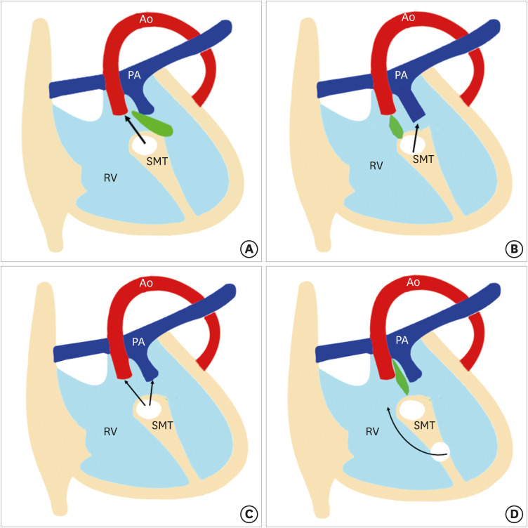
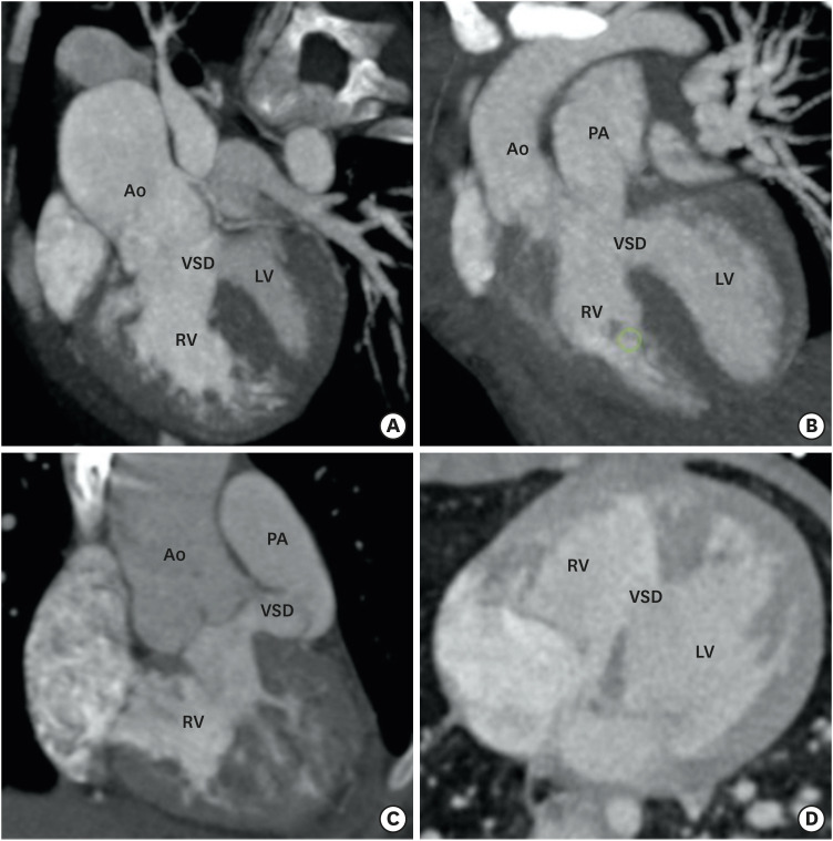
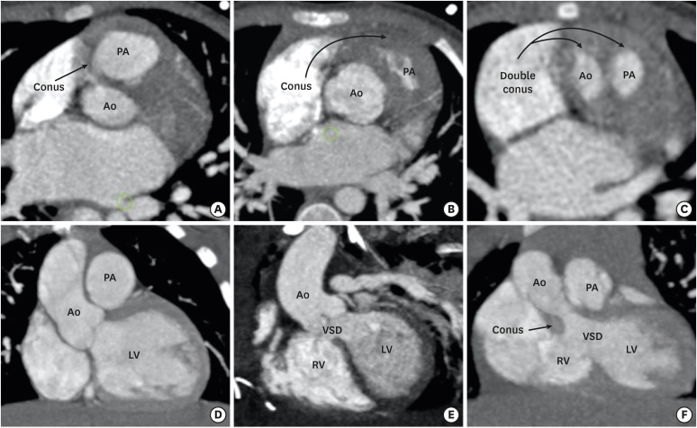
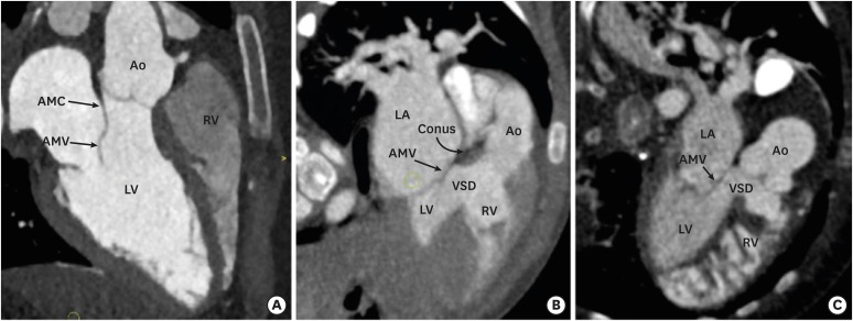
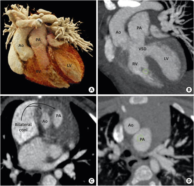
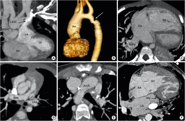
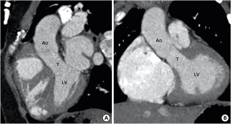
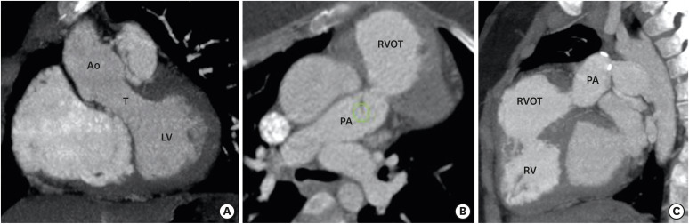
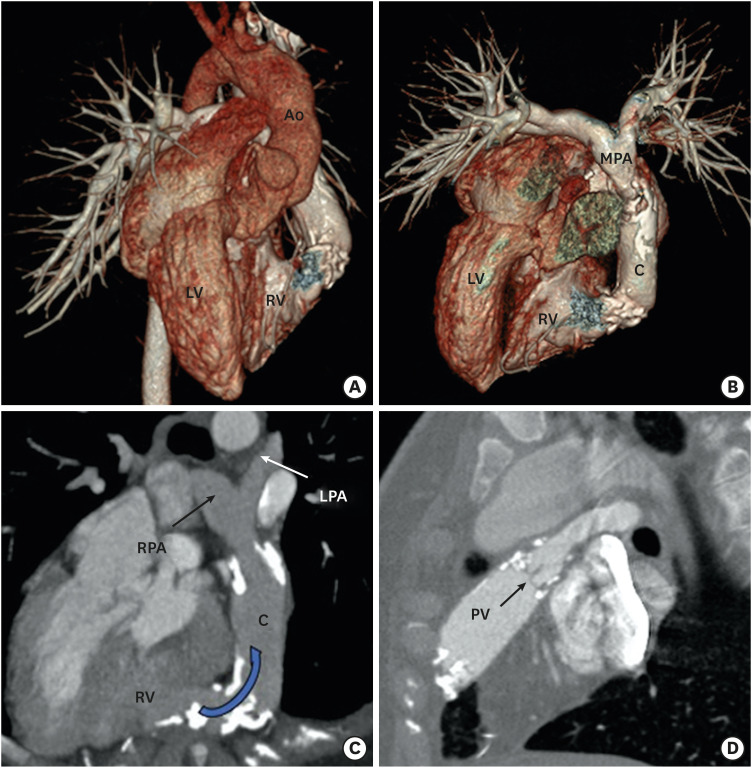
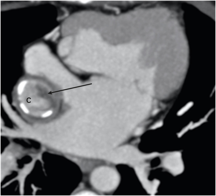
Double-outlet right ventricle (DORV) is a type of ventriculoarterial connection in which both great arteries arise entirely or predominantly from the right ventricle. The morphology of DORV is characterized by a ventricular septal defect (location and relationship with the semilunar valve); bilateral coni and aortomitral continuity; the presence or absence of outflow tract obstruction; tricuspid-pulmonary annular distance; and associated cardiac anomalies. The surgical approach varies with the type of DORV and is based on multiple variables. Computed tomography (CT) is a robust diagnostic tool for the preoperative and postoperative assessment of DORV. Unlike echocardiography and magnetic resonance imaging (MRI), CT imaging is not limited by small acoustic window, need for anaesthesia and can be used in patients with metallic implants. Current generations CT scanners with high spatial and temporal resolution, wide detectors, high-pitch scanning mode, dose-reduction algorithms, and advanced three-dimensional post-processing tools provide a low-risk, high-quality alternative to diagnostic cardiac catheterization or MRI, and have been increasingly utilized in nearly every type of congenital heart defect, including DORV.

Keywords: Congenital heart disease; Double outlet right ventricle.


Conflict of interest statement

The authors have no financial conflicts of interest.

Figures

Figure 1
Figure 1. Four types of VSDs. The relationship between the outlet septum (green) and SMT defines the location of the VSD. In subaortic VSD, (A) the outlet septal attaches to the anterior limb of the septal band. In subpulmonic VSD, (B) the outlet septal attaches to the posterior limb of the septal band. In the doubly committed VSD, and (C) the outlet septum is absent. (D) A remote VSD is not related to the outlet septum and the distance between the VSD and the semilunar valve is greater than the size of the aortic valve.
RV: right ventricle, SMT: septomarginal trabecula, VSD: ventricular septal defect.
Figure 2
Figure 2. Types of VSD. (A) A reformatted coronal CT angiography image indicates the subaortic position of VSD. (B) A reformatted coronal CT angiography image indicates the subpulmonic position of the VSD. (C) A reformatted coronal CT angiography image indicates the doubly committed VSD. The VSD is located in relationship to both semilunar valves. (D) An axial CT angiography image shows the remote intramuscular VSD.
Ao: aorta, CT: computed tomography, LV: left ventricle, PA: pulmonary artery, RV: right ventricle, VSD: ventricular septal defect.
Figure 3
Figure 3. Conus (infundibulum). (A, D) Axial and coronal CT angiography images show a subpulmonic conus in a normal individual. (B, E) Axial and coronal CT angiography images indicate the subpulmonic conus in a patient with TOF. The subaortic conus is absent. Absence of the subaortic conus is used to differentiate a TOF from a DORV in the gray zone. (C, F) Axial and coronal CT angiography images indicate the double coni (subpulmonic and subaortic) in a patient with a DORV.
Ao: aorta, CT: computed tomography, DORV: double-outlet right ventricle, LV: left ventricle, PA: pulmonary artery, RV: right ventricle, TOF: tetralogy of Fallot, VSD: ventricular septal defect.
Figure 4
Figure 4. Aortomitral continuity. (A) A reformatted coronal CT angiography image indicates a preserved AMC in a normal individual. Fibrous continuity is evident between the noncoronary and left coronary leaflets of the aortic valve and AML. (B) A reformatted coronal CT angiography image indicates a preserved aortomitral continuity in a patient with a TOF. (C) A reformatted coronal CT angiography image indicates the loss of aortomitral continuity in a patient with a DORV. The subaortic conus is visible between the aortic valve and anterior mitral leaflet.
Ao: aorta, AMC: aortomitral continuity, AML: anterior mitral leaflet valve, AMV: anterior mitral valve, CT: computed tomography, DORV: double-outlet right ventricle, LA: left atrium, LV: left ventricle, PA: pulmonary artery, RV: right ventricle, TOF: tetralogy of Fallot, VSD: ventricular septal defect.
Figure 5
Figure 5. Great-vessel relationship. (A) An axial CT angiography image indicating the posterior and rightward location of the Ao to the PA (normal relationship). (B) An axial CT angiography image indicates the anterior and rightward location of the Ao to the PA (D-TGA type). (C) An axial CT angiography image indicating the side-by-side and leftward orientation of the Ao to PA (cc-TGA type).
Ao: aorta, cc-TGA: congenitally corrected transposition of the great artery, CT: computed tomography, PA: pulmonary artery.
Figure 6
Figure 6. RVOT obstruction. A sagittal reformatted CT image indicating mild RVOT obstruction. CT: computed tomography, PA: pulmonary artery, RV: right ventricle, RVOT: right ventricular outflow tract.
Figure 7
Figure 7. Example of left ventricular systolic function calculated using short- and long-axis images from dual-source CT coronary angiography.
CT: computed tomography, ED: end-systolic, ES: end-systolic, LV: left ventricle.
Figure 8
Figure 8. TOF-type DORV. A cinematic rendered image (A) demonstrating both the great arteries arising from a right ventricle with severe stenosis of the proximal pulmonary artery. A coronal reformatted (B) and front-cut VRT image (C) showing subaortic VSD. Sagittal (D) and axial-reformatted (E) CT images showing great-vessel relationship. The Aorta is rightwards and posterior to the pulmonary trunk, with the conal septum separating them. Hypertrophy of the pulmonic infundibulum causing severe RVOT stenosis is evident. The aortic valve appears to be bicuspid. A coronal reformatted CT image (F) shows an associated extracardiac anomaly as a diaphragmatic defect, with herniation of the left hepatic lobe (*) into the thoracic cavity.
Ao: aorta, CT: computed tomography, DORV: double-outlet right ventricle, LA: left atrium, LV: left ventricle, PA: pulmonary artery, RA: right atrium, RV: right ventricle, RVOT: right ventricular outflow tract, TOF: tetralogy of Fallot, VRT: volume rendering technique, VSD: ventricular septal defect.
Figure 9
Figure 9. TGA-type DORV. (A) A cinematic rendered image demonstrating both great arteries arising from RV. The great-vessel trunks run parallel to each other, with the aorta on the right side. (B) A coronal reformatted image showing subpulmonic VSD. (C) An axial reformatted CT image showing bilateral coni. The conal septum separates the great vessels. (D) An axial reformatted CT image demonstrating great-vessel relationship. The aorta is anterior to and on the right side of the pulmonary trunk (D-TGA type).
Ao: aorta, CT: computed tomography, LV: left ventricle, PA: pulmonary artery, RA: right atrium, RV: right ventricle, VSD: ventricular septal defect.
Figure 10
Figure 10. Associated cardiac anomalies. (A) A coronal CT image demonstrating LSVC draining into left atrium. (B) VRT image showing coarctation of the aorta. (C) Am axial CT image showing partial anomalous pulmonary venous return. The right inferior pulmonary vein is draining into right atria. The right atria and ventricle are dilated. (D) An oblique reformatted CT image showing stenosis of the osteoproximal part of the left pulmonary artery. (E) An axial CT image showing right-sided aortic arch. (F) An axial CT image shows mitral atresia.
Ao: aorta, CT: computed tomography, LA: left atrium, LPA: left pulmonary artery, LSVC: left-sided superior vena cava, LV: left ventricle, MV: mitral valve, PA: pulmonary artery, RA: right atrium, RV: right ventricle, RIPV: right inferior pulmonary vein, RPA: right pulmonary artery, RSVC: right-sided superior vena cava, RV: right ventricle, VRT: volume rendering technique, VSD: ventricular septal defect.
Figure 11
Figure 11. Postoperative appearance of DORV. Sagittal (A) and coronal (B) reformatted CT angiography images demonstrating intraventricular tunnel created to channel blood flow from the LV to the aorta through ventricular septal defect. No evidence of any stenosis seen.
Ao: aorta, CT: computed tomography, DORV: double-outlet right ventricle, LV: left ventricle, T: tunnel.
Figure 12
Figure 12. Postoperative appearance of DORV. (A) Coronal reformatted CT angiography image indicating an intraventricular tunnel to channel blood flow from the LV to the aorta through the ventricular septal defect. No evidence of any stenosis is visible. Oblique (B) and sagittal (C) CT angiography images indicating pulmonary stenosis with bulging of the RVOT, suggesting an RVOT aneurysm. The RV is dilated.
Ao: aorta, CT: computed tomography, DORV: double-outlet right ventricle, LV: left ventricle, PA: pulmonary artery, RV: right ventricle, RVOT: right ventricular outflow tract, T: tunnel.
Figure 13
Figure 13. Postoperative (Rastelli operation) appearance in a case of a DORV with cc-TGA. VRT image (A) and VRT image after removing Ao (B) showing cc-TGA morphology. The aorta is arising from right-sided LV. The RV is on the left side. A conduit is seen between the left-sided RV and the MPA. (C) An oblique reformatted MIP CT image showing dense calcification with moderate stenosis at the RV anastomotic site of the conduit. (D) An oblique reformatted CT image showing native pulmonary valve in the closed position. Mild calcification of the pulmonary valve leaflets is also seen.
Ao: aorta, C: conduit, cc-TGA: congenitally corrected transposition of the great artery, CT: computed tomography, DORV: double-outlet right ventricle, LPA: left pulmonary artery, MIP: maximum intensity projection, MPA: main pulmonary artery, RV: right ventricle, LV: left ventricle, PV: pulmonary valve, RPA: right pulmonary artery, VRT: volume rendering technique.
Figure 14
Figure 14. Postoperative (Fontan repair) appearance in a DORV. An axial MIP image showing eccentric hypodensity in an extra-atrial Fontan conduit that persists in a delayed venous phase, suggesting thrombosis (arrow).
C: conduit, DORV: double-outlet right ventricle, MIP: maximum intensity projection.

Similar articles

Cited by

References

    1. Walters HL, 3rd, Mavroudis C, Tchervenkov CI, Jacobs JP, Lacour-Gayet F, Jacobs ML. Congenital Heart Surgery Nomenclature and Database Project: double outlet right ventricle. Ann Thorac Surg. 2000;69:S249–63. - PubMed
    1. Smallhorn JF. Double-outlet right ventricle: an echocardiographic approach. Semin Thorac Cardiovasc Surg Pediatr Card Surg Annu. 2000;3:20–33. - PubMed
    1. Elster A. Impact of new technologies on dose reduction in CT. In: Osborn AG, Abbara S, Elster AD, et al., editors. Yearbook of Diagnostic Radiology. St. Louis, MO: Mosby; 2011. pp. 191–192. - DOI
    1. Lacour-Gayet F, Haun C, Ntalakoura K, et al. Biventricular repair of double outlet right ventricle with non-committed ventricular septal defect (VSD) by VSD rerouting to the pulmonary artery and arterial switch. Eur J Cardiothorac Surg. 2002;21:1042–1048. - PubMed
    1. Sridaromont S, Feldt RH, Ritter DG, Davis GD, Edwards JE. Double outlet right ventricle: hemodynamic and anatomic correlations. Am J Cardiol. 1976;38:85–94. - PubMed