. 2021 Jun 3;11(1):11770.
doi: 10.1038/s41598-021-91148-9.

Establishment of an integrated automated embryonic manipulation system for producing genetically modified mice

Affiliations

Establishment of an integrated automated embryonic manipulation system for producing genetically modified mice

Tomoo Eto et al. Sci Rep. .

Abstract

Genetically modified mice are commonly used in biologic, medical, and drug discovery research, but conventional microinjection methods used for genetic modification require extensive training and practical experience. Here we present a fully automated system for microinjection into the pronucleus to facilitate genetic modification. We first developed software that automatically controls the microinjection system hardware. The software permits automatic rotation of the zygote to move the pronucleus to the injection pipette insertion position. We also developed software that recognizes the pronucleus in 3-dimensional coordinates so that the injection pipette can be automatically inserted into the pronucleus, and achieved a 94% insertion rate by linking the 2 pieces of software. Next, we determined the optimal solution injection conditions (30 hPa, 0.8-2.0 s) by examining the survival rate of injected zygotes. Finally, we produced transgenic (traditional DNA injection and piggyBac Transposon system) and knock-in (genomic editing) mice using our newly developed Integrated Automated Embryo Manipulation System (IAEMS). We propose that the IAEMS will simplify highly reproducible pronuclear stage zygote microinjection procedures.


Conflict of interest statement

The authors declare no competing interests.

Figures
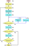
Figure 1
Figure 1
Sequence required for fully automated solution injection. The sequence involves detection of the injection target and judgment of the work at each step (yellow), and then execution of the work (blue). (A) Command the controller (Computer) to start the fully automated operation. (B) Detect the coordinates of the current positions of the pipettes. (C) Detect the zygote position. (D) Move the pipette to the zygote position. (E) Hold the zygote in the holding pipette and release the zygote once to adjust the holding pressure. (F) Detect the current position of the pronucleus. If the pronucleus cannot be detected, change the height of the holding pipette while holding the zygote (F2), and then re-detect the pronucleus (F). If the pronucleus is not detected after performing sequence F2 multiple times, use an injection pipette to rotate the zygote vertically (F3) and then re-detect the pronucleus (F). (G) Insert the injection pipette into the pronucleus. (H) If, after injection of the solution, the nuclear membrane adheres to the injection pipette and does not come off, then stop the procedure(K). Remove the nuclear membrane from the injection pipette and restart (A). (I) Move the zygote to the release area and release the zygote (Fig. S3). (J) Check whether the injection has been performed on all zygotes. If an injection zygote remains that has not been injected, return to sequence C and continue injecting. (K) After injecting the solution into all available zygotes, stop the fully automated injection process.
Figure 2
Figure 2
Hardware. The hardware was created by connecting an electric injector to an electric manipulation system, and comprises 3 main elements: input device (red), controller (yellow), and output device (blue). In the hardware, when the signal is input from the outside (A), the controller analyzes the signal (B), the electric distribution board controls multiple machines according to the analyzed data (C) and operates multiple electric machines (D,E). (D) The electric manipulator moves the pipettes 3-dimensionally (D1), the electric sample stage moves the dish containing the zygotes 2-dimensionally (D2), and the electric pump increases or decreases the holding pressure in the holding pipette (D3). (E) The electric injector injects the solution by applying the injection pressure for the amount of time that was previously set in the controller. Only the electric injector (E) operates with a serial communication from the controller (B). In a fully automated operation, when the start button (A1) signal is input to the controller, multiple machines (D,E) operate electrically based on the microscope image acquired by the microscope camera (A3). In manual mode, the operator manually operates the joystick (A2) while looking at the display (F) to enter operational commands into the controller (B) to electrically operate multiple machines (manipulator (D1), sample stage (D2), and pump (D3)). In addition, in solution injection, the operator manually inputs the operation signal directly to the electric injector (E).
Figure 3
Figure 3
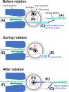
Procedure to fully rotate the zygote to move the pronucleus to the injection pipette insertion position. (A) Before rotation, the zygote is held in the holding pipette under a state of increased holding pressure. The injection pipette is held stationary at the middle height position of the zygote. (B) If the pronucleus inside the zygote is outside the range (red dotted square) where automated solution injection is possible. (C) The injection pipette automatically moves to the upper part of the zygote opposite the pronucleus. (D) Due to the decreased holding pressure, the zygote disengages from the holding pipette, and immediately lowering the injection pipette causes the zygote to rotate. (E) With the rotation, the pronucleus moves from the corner of the zygote to the center (red arrow). (F) Immediately after rotation, the holding pressure is increased to hold the zygote. (G) The injection pipette is returned to its initial position (A). (H) When the pronucleus is within the range for automated solution injection (red dotted square), the injection pipette is inserted into the pronucleus.
Figure 4
Figure 4
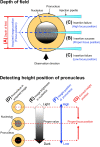
Procedure for detecting the height position of the center of the pronucleus during automated solution injection. (A) Under microscope observation, the depth of field (red arrow) varies, so the focus position of the acquired image and the height position of the pronucleus may be different each time. (B) If the nucleolus is identified at the proper focus position for pipette insertion, the pipette can be inserted. (C) On the other hand, if there is a difference in height between the focus position and pronucleus position, the nuclear membrane will not break and the pipette cannot be inserted. To ensure that the pipette is placed at the proper position, it is necessary to detect and correct the height position of the pronucleus. (F) From the pronucleus in the acquired image (D), obtain the brightness value of the nucleolus (E), and detect the height position of the pronucleus. (G) If a height position other than the proper focus position is detected, correct the proper focus position and insert the pipette.
Figure 5
Figure 5
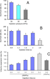
Injection pressure and injection duration influence the zygote survival rate and expansion rate. (A) The infusion time was fixed at 0.8 s and zygote survival was examined at infusion pressures of 30, 35, and 45 hPa. (B) With a constant pressure of 30 hPa, zygote survival was examined at injection times of 0.8, 1.2, 1.6, 2.0, and 2.4 s. (C) The pronuclear volume expansion rate when injected at the indicated pressure.
Figure 6
Figure 6
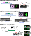
EGFP expression and gene transfer in genetically modified mice produced by 3 different methods. Different DNA constructs were used to produce the 3 types of genetically modified mice. Mice produced by fully automated or manual injection were examined for EGFP expression by UV irradiation and for gene modification by genomic DNA PCR. Yellow arrows indicate typical examples of testes and ovaries containing germ cells with confirmed EGFP fluorescence. Blue arrows indicate typical examples of ovaries or testes before UV irradiation. EGFP fluorescence-positive mice were always positive on PCR examination.
Figure 7
Figure 7
Survival and in vitro development of zygotes injected into the pronucleus with solutions used for 3 different genetic modifications. In the fully automated solution injection, all injection pressures were fixed at 30 hPa, and the injection time was 0.8 or 1.6 s for traditional DNA injection (traditional DI), and 1.6 s for the piggyBac Transposon system (piggyBac TS) and CRISPR-Cas9 system (knock-in). In addition, the piggyBac TS used solutions with a DNA concentration of 2 or 10 ng/µl. The survival rate (A) and development rate to a 2-cell stage embryo (B) after solution injection did not differ significantly among groups with fully automated and manual injections.

Similar articles

Cited by

References

    1. Kersten K, de Visser KE, van Miltenburg MH, Jonkers J. Genetically engineered mouse models in oncology research and cancer medicine. EMBO Mol. Med. 2017;9:137–153. doi: 10.15252/emmm.201606857. - DOI - PMC - PubMed
    1. Davey RA, MacLean HE. Current and future approaches using genetically modified mice in endocrine research. Am. J. Physiol. Endocrinol. Metab. 2006;291:E429–438. doi: 10.1152/ajpendo.00124.2006. - DOI - PubMed
    1. Liggett SB. Genetically modified mouse models for pharmacogenomic research. Nat. Rev. Genet. 2004;5:657–663. doi: 10.1038/nrg1429. - DOI - PubMed
    1. Babinet C. Transgenic mice: an irreplaceable tool for the study of mammalian development and biology. J. Am. Soc. Nephrol. 2000;11:S88–S94. doi: 10.1681/ASN.V11suppl_2s88. - DOI - PubMed
    1. Gordon JW, Scangos GA, Plotkin DJ, Barbosa JA, Ruddle FH. Genetic transformation of mouse embryos by microinjection of purified DNA. Proc. Natl. Acad. Sci. USA. 1980;77:7380–7384. doi: 10.1073/pnas.77.12.7380. - DOI - PMC - PubMed