Review
. 2021 Jun 8;50(11):6541-6568.
doi: 10.1039/d0cs01541e.

Atomically precise graphene nanoribbons: interplay of structural and electronic properties

Affiliations
Review

Atomically precise graphene nanoribbons: interplay of structural and electronic properties

R S Koen Houtsma et al. Chem Soc Rev. .

Abstract

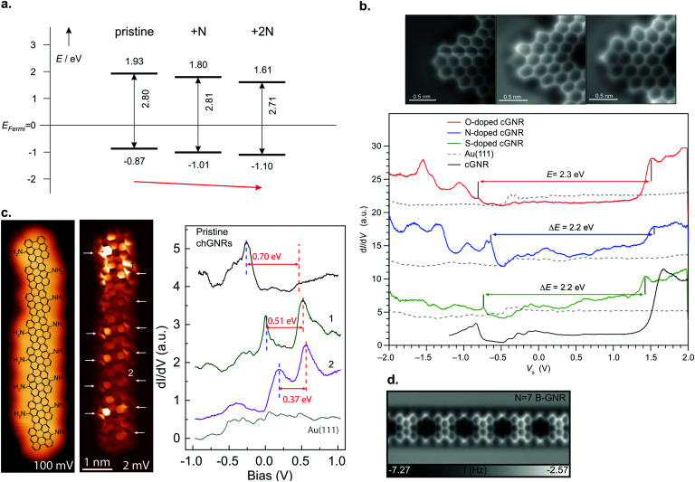
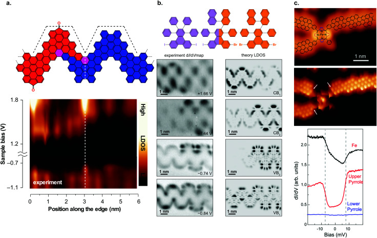
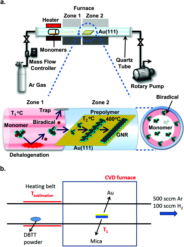
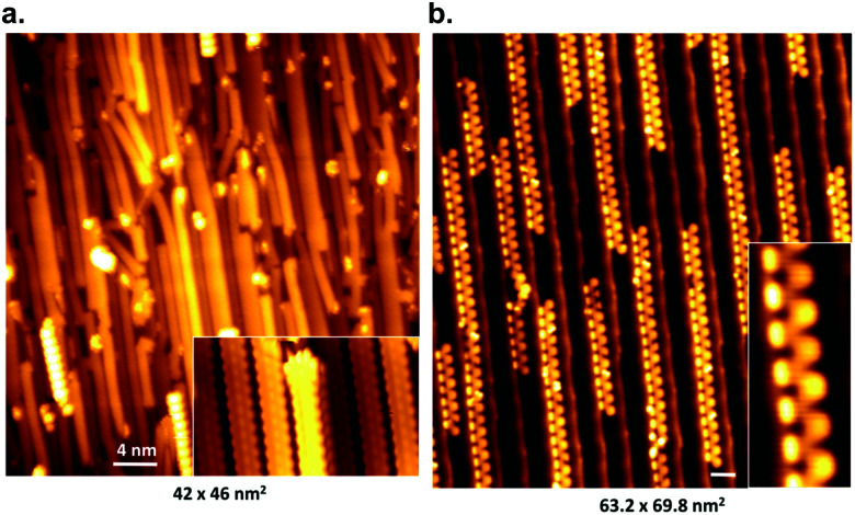
Graphene nanoribbons hold great promise for future applications in nanoelectronic devices, as they may combine the excellent electronic properties of graphene with the opening of an electronic band gap - not present in graphene but required for transistor applications. With a two-step on-surface synthesis process, graphene nanoribbons can be fabricated with atomic precision, allowing precise control over width and edge structure. Meanwhile, a decade of research has resulted in a plethora of graphene nanoribbons having various structural and electronic properties. This article reviews not only the on-surface synthesis of atomically precise graphene nanoribbons but also how their electronic properties are ultimately linked to their structure. Current knowledge and considerations with respect to precursor design, which eventually determines the final (electronic) structure, are summarized. Special attention is dedicated to the electronic properties of graphene nanoribbons, also in dependence on their width and edge structure. It is exactly this possibility of precisely changing their properties by fine-tuning the precursor design - offering tunability over a wide range - which has generated this vast research interest, also in view of future applications. Thus, selected device prototypes are presented as well.


Conflict of interest statement

The authors declare no competing interests.

Figures

Fig. 1
Fig. 1. (a) Various GNR types and their classification. (b) Schematic overview of on-surface GNR fabrication for the case of a 7-AGNR.
Fig. 2
Fig. 2. Precursor design determines the final product. (a) Schematic overview of the Ullmann coupling reaction in dependence of precursor design. X represents a halogen atom. Adapted with permission from ref. 49. Copyright 2017, the Royal Society of Chemistry. (b) Synthesis of a GNR from a precursor with halogen substitutions in opposite positions leading to an AGNR. The example depicts the formation of a 7-AGNR from dibromo-bianthryl together with a high-resolution non-contact (nc) atomic force microscopy (AFM) image recorded with a CO-functionalized tip. Adapted with permission from ref. 179. Copyright 2013, Springer Nature. (c) Synthesis of a GNR from a precursor having the halogens in the ‘meta’ position together with a high-resolution nc-AFM image recorded with a CO-functionalized tip. Steric repulsion prevents the formation of a cyclic nanographene. Adapted with permission from ref. 58. Copyright 2016, Springer Nature.
Fig. 3
Fig. 3. Register of precursors used so far for atomically precise GNR formation together with the resulting GNR structure. (a) Armchair GNRs, excluding ones resulting from the lateral fusion of ribbons. (b) Chevron-like GNRs. (c) Chiral GNRs. (d) Cove-edged GNRs, (e) zigzag GNRs. (f) Porous GNR. (g) GNRs with embedded topological states. (h) GNRs with other edge topology.
Fig. 4
Fig. 4. Electronic properties of graphene nanoribbons. (a) Formation of the band structure of GNRs by selecting cuts along allowed k-values for a 9-AGNR. Reprinted with permission from ref. 57. Copyright 2017, American Chemical Society. (b) LDA-DFT calculations of AGNR band gaps and quasiparticle correction. Reprinted figure with permission from ref. 118. Copyright 2007 by the American Physical Society. (c) Electronic structure of ZGNRs from LSDA-DFT calculations, showing the spin-polarized edge state, formation of a band gap and band gap as a function of ribbon width. Reprinted figure with permission from ref. 29. Copyright 2006 by the American Physical Society. (d) Band structure of various zigzag, chiral and armchair GNRs from tight-binding calculations. Reprinted figure with permission from ref. 135. Copyright 2011 by the American Physical Society. (e) Mean-field Hubbard model calculations for a (2,1) chiral GNR, showing the opening of a band gap. Reprinted figure with permission from ref. 135. Copyright 2011 by the American Physical Society.
Fig. 5
Fig. 5. (a) Lateral fusion of poly(p-phenylene) wires leads to formation of 3p-AGNRs. Reprinted with permission from ref. 112. Copyright 2017, American Chemical Society. Provided under an ACS AuthorChoice License, requests for further permissions should be directed to the American Chemical Society. (b) Long 9-AGNRs formed on Au(111) from an iodine functionalized precursor. Reprinted with permission from ref. 82. Copyright 2017, American Chemical Society. (c) STS spectra for 9-, 14-, 18- and 21-AGNRs on Si/Au(111) from which the band gap can be determined. Reprinted with permission from ref. 114. Copyright 2017, American Chemical Society.
Fig. 6
Fig. 6. Electronic properties of 7-AGNRs. (a) ARPES data of aligned 7-AGNRs on Au(788). In the left panel 3 dispersive bands are marked by white arrows. The right panel shows a parabolic fit (black line) from which mVB = 0.21 me is extracted. The white curve indicates the carrier velocity. Reprinted with permission from ref. 78. Copyright 2012, American Chemical Society. (b) FT-STS for 7-AGNR on a monolayer NaCl on Au(111). The bottom left panel shows STS spectra taken along the black dashed line indicated in the top image. Bulk as well as end states are visible. The bottom right panel shows the Fourier transform of the bottom left panel. Dispersive bands around −1 eV and +2 eV are visible, as well as two non-dispersive bands around −0.5 eV and +1.4 eV corresponding to the end states. Adapted with permission from ref. 180. Copyright 2016, the Authors, published by Springer Nature. Provided under a Creative Commons CC BY 4.0 international license. (c) Conductance map for 7-AGNR on NaCl on Au(111). For small (<∼0.5 nm) tip-sample distances, there is some in gap, non-resonant tunneling present. At larger tip-sample distances, only resonant tunneling can be observed. Adapted with permission from ref. 73. Copyright 2018, American Chemical Society.
Fig. 7
Fig. 7. (a) nc-AFM image of an edge extended cGNR synthesized from 46. Reproduced with permission from ref. 201. Copyright 2019, Wiley-VCH. (b) Nanoporous graphene from lateral fusion of cGNRs using 38 (X = C) as a precursor. Reprinted with permission from ref. 117. Copyright 2020, American Chemical Society. (c) Nitrogen and boron doped chevron-like GNRs with partial zigzag edges fabricated from precursors 48 (right) and 50 (left). Reproduced with permission from ref. 203. Copyright 2020, the Authors, published by Wiley-VCH. Provided under a Creative Commons CC BY 4.0 international license. (d) Formation of (3,1)-chGNRs on Cu(111) based on the suggested synthesis of Sánchez-Sánchez et al. (ref. 72). (e) nc-AFM image of a (3,1) chiral GNR formed from 9,9′-bianthracene (8 without halogen substitutions) on Cu(111). Reprinted with permission from ref. 208. Copyright 2017, American Chemical Society. (f) dI/dV maps of the valence and conduction band of the (3,1) ch-GNR on Au(111). Reprinted with permission from ref. 209. Copyright 2017, American Chemical Society. (g) dI/dV maps of (3,1)-chGNR on NaCl. The top row reports the simulated data and the bottom row the experimental data. Reprinted with permission from ref. 73. Copyright 2018, American Chemical Society.
Fig. 8
Fig. 8. GNRs with unconventional topologies. (a) Porous GNRs (70) hosting a regular array of vacancies. High-resolution nc-AFM und STM images (left), together with their electronic structure (right). Reprinted with permission from ref. 210. Copyright 2020, American Chemical Society. (b) Electronic structure of sawtooth GNRs (76) revealing a zero-mode band at the Fermi level (marked with 2 at 0 V). The red spectrum (top image) was taken at the position indicated in the inset. The three lower images display the dI/dV maps recorded at the energies indicated by arrows in the top image. From ref. 41. Reprinted with permission from the American Association for the Advancement of Science. Copyright 2020, the Authors. (c) Electronic properties of pyrene-based GNRs (78) (STM image to the left) revealing their narrow band gap (line spectra to the right, taken along the green arrow given in the STM image). Reproduced with permission from ref. 213. Copyright 2020, Wiley-VCH.
Fig. 9
Fig. 9. (a) Summary of band alignment of nitrogen doped cGNRs on Au(111) investigated by a combination of HREELS and UPS. Pristine (2N) corresponds to 30 (34), while 1N corresponds to a monomer with one pyridyl group. Reproduced with permission from ref. 39. Copyright 2013, Wiley-VCH. (b) Doping of cGNRs with (left to right) NH, O and S. The nc-AFM images detail the different appearances (left) while the right panel displays the respective STS spectra in comparison to a pristine cGNR. cGNR (doped cGNR) corresponds to 31 (39) in Fig. 3. Adapted with permission from ref. 200. Copyright 2017, American Chemical Society. (c) From left to right: STM image of an NH2 doped (3,1)-chGNR with overlaid structure model. Same area imaged with a CO-functionalized tip. STS spectra taken at the positions indicated in the STM image. Reprinted with permission from ref. 216. Copyright 2020, American Chemical Society. (d) nc-AFM image of a boron doped 7-AGNR. The boron substitutions appear dark in the image. Reproduced with permission from ref. 219. Copyright 2015, the Authors, originally published by Springer Nature. Provided under a Creative Commons CC BY 4.0 international license.
Fig. 10
Fig. 10. GNR heterostructures. (a) Structural model of a heterojunction between carbonyl-functionalized and pristine chevron GNRs together with dI/dV line spectra taken across the junction area. The formation of a type II heterojunction can be inferred from the dI/dV spectra. Reproduced with permission from ref. 92. Copyright 2017, Springer Nature. (b) Hierarchical formation of GNR heterojunctions through the use of a linker molecule. Below the structural model, the dI/dV maps on the junction area are shown together with the calculated LDOS. The dI/dV maps reveal that the frontier states are confined to one side of the junction. Adapted with permission from ref. 89. Copyright 2018, American Chemical Society. (c) Junction between three (3,1) ch-GNRs and an Fe porphyrin derivative. dI/dV spectra reveal that the spin state of the Fe atom is preserved upon contact with the GNRs. Reproduced with permission from ref. 226. Copyright 2018, the Authors, published by the American Association for the Advancement of Science. Provided under a Creative Commons CC BY-NC 4.0 international license.
Fig. 11
Fig. 11. Chemical vapour deposition setups. (a) Three-stage setup developed by Sakaguchi et al. It is evacuated by a rotary pump and fed with Argon gas to a pressure of 1 torr. Stage 1: the precursor molecules are placed in a quartz boat from which they are evaporated at 250 °C. Stage 2: the precursors collide with the quartz tube wall kept at 350 °C and are dehalogenated. Stage 3: the dehalogenated precursors arrive at the Au(111)/mica substrate, which is held at 250 °C, and form polymer intermediates. These are converted to GNRs by raising the temperature of zone 2 to 400 °C. Reproduced with permission from ref. 246. Copyright 2014, Wiley-VCH. (b) Two-stage setup developed by Chen et al., which is kept at ambient pressure in a mixed argon/hydrogen atmosphere. Stage 1: the precursor is evaporated from a heating belt. Stage 2: the precursor is deposited on the Au/mica substrate, which is kept at 250 °C to form polymer intermediates. The polymers are converted to GNRs by increasing the temperature to 450 °C. Reprinted with permission from ref. 247. Copyright 2016, American Chemical Society.
Fig. 12
Fig. 12. STM images of aligned graphene nanoribbons on Au(788), scale bars 4 nm. (a) 7-AGNR and (b) cGNRs (31). Reprinted figure with permission from ref. 77. Copyright 2012 by the American Physical Society.
Fig. 13
Fig. 13. Schematic of the octanethiol-intercalation transfer method. (i) Aligned GNRs on Au(788). (ii) An HSQ support layer is spin-coated on the GNRs. (iii) The stack is submerged in an octanethiol solution. (iv) Octanethiol intercalates between GNRs and Au. (v) Thermal release tape is used to pick up the HSQ/GNR stack. (vi) Overnight immersion in water removes residual octanethiol molecules. (vii) The tape/HSQ/GNR stack is placed on SiO2/Si; the tape is removed by annealing at 120 °C. (viii) The HSQ support layer is removed by a 25% TMAH developer. Reprinted from ref. 79, with the permission of AIP Publishing. Copyright 2018, the Authors.
Fig. 14
Fig. 14. (a) Schematic of a GNR-based field effect transistor with graphene electrodes. The drain and source are metal electrodes deposited on the graphene electrodes. Reprinted from ref. 251. Copyright 2019, with permission from Elsevier. (b–d) Comparison of drain current vs drain voltage characteristics for three 7-AGNR FETs. (b) FET with a channel length L = 60 nm, width W = 50 μm, GNRs parallel to the channel. (c) FET with a channel length L = 20 nm, W = 500 nm, GNRs parallel to the channel. (d) FET with a channel length L = 20 nm, W = 500 nm, GNRs perpendicular to the channel. Reprinted from ref. 79, with the permission of AIP Publishing. Copyright 2018, the Authors.
None
R. S. Koen Houtsma
None
Joris de la Rie
None
Meike Stöhr

References

    1. Geim A. K. Novoselov K. S. Nat. Mater. 2007;6:183–191. - PubMed
    1. Papageorgiou D. G. Kinloch I. A. Young R. J. Prog. Mater. Sci. 2017;90:75–127.
    1. Castro Neto A. H. Guinea F. Peres N. M. R. Novoselov K. S. Geim A. K. Rev. Mod. Phys. 2009;81:109.
    1. Zhang T. Wu S. Yang R. Zhang G. Front. Phys. 2017;12:127206.
    1. Schwierz F. Nat. Nanotechnol. 2010;5:487. - PubMed