. 2021 Jun;8(11):e2004338.
doi: 10.1002/advs.202004338. Epub 2021 Mar 18.

Triple Stiffness: A Bioinspired Strategy to Combine Load-Bearing, Durability, and Impact-Resistance

Affiliations

Triple Stiffness: A Bioinspired Strategy to Combine Load-Bearing, Durability, and Impact-Resistance

Ali Khaheshi et al. Adv Sci (Weinh). 2021 Jun.

Abstract

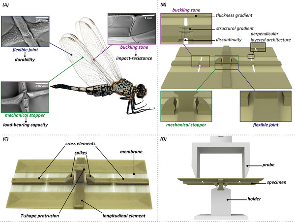
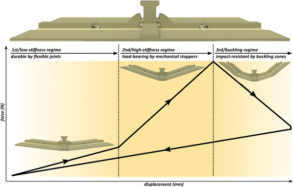
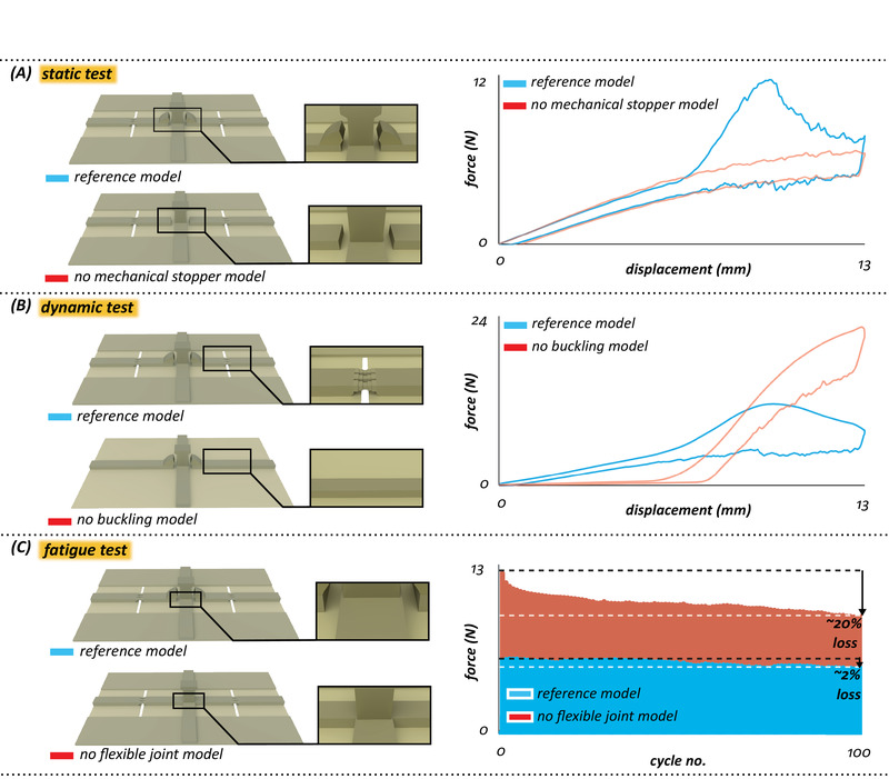
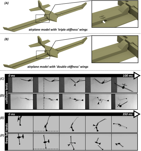
Structures with variable stiffness have received increasing attention in the fields of robotics, aerospace, structural, and biomedical engineering. This is because they not only adapt to applied loads, but can also combine mutually exclusive properties. Here inspired by insect wings, the concept of "triple stiffness" is introduced and applied to engineering systems that exhibit three distinct deformability regimes. By implementing "flexible joints," "mechanical stoppers," and "buckling zones," structures are engineered to be not only load-bearing and durable, but also impact-resistant. To practice the performance of the design concept in real-life applications, the developed structures are integrated into 3D printed airplane wing models that withstood collisions without failure. The concept developed here opens new avenues for the development of structural elements that are load-bearing, durable, and impact-resistant at the same time.

Keywords: adaptive systems; buckling; deformability regimes; tuneable stiffness; variable rigidity.


Conflict of interest statement

The authors declare no conflict of interest.

Figures

Figure 1
Figure 1
Inspiration, design, fabrication and mechanical testing of “triple stiffness” structures. A) Design strategies of a dragonfly (Acisoma panorpoides, Reproduced with permission.[ 17 ] Copyright 2018, Elsevier) wing: flexible joint, mechanical stopper (i.e., spike), and buckling zone (i.e., costal break or nodus). B) Wing‐inspired design strategies included in the “reference model.” C) 3D printed prototype of the “reference model” with the indication of the key structural elements. D) Experimental setup used in the static, dynamic, and fatigue tests.
Figure 2
Figure 2
Schematic force‐displacement graph of the “reference model.” The plot shows three different deformability regimes due to the inclusion of three design strategies of the flexible joints, mechanical stoppers, and buckling zones. The initial state of the “reference model” before loading is demonstrated above the graph.
Figure 3
Figure 3
Mechanical behavior of the “reference model” versus “no mechanical stopper model,” “no buckling model,” and “no flexible joint model.” A) Force–displacement curves obtained from static tests for the “reference model” and “no mechanical stopper model.” B) Force–displacement curves obtained from dynamic tests for the “reference model” and “no buckling model.” C) Force‐cycle diagrams obtained from fatigue tests for the “reference model” and “no flexible joint model.”. The illustrated graphs are the average data of three specimens from each experiment.
Figure 4
Figure 4
Design of the airplane models and their performance in impact tests. A) A perspective view of the airplane model with “triple stiffness” wings. B) A perspective view of airplane model with “double stiffness” wings. C,D) Collision tests. Snapshots from high‐speed video recordings of collision tests on the airplane model with C) “triple stiffness” wings and on the airplane model with D) “double stiffness” wings. E,F) Free fall tests. Snapshots from high‐speed video recordings of free fall tests on the airplane model with E) “triple stiffness” wings and on the airplane model with F) “double stiffness” wings. The arrowheads indicate the occurrence of the buckling and fracture in the airplane models with “triple stiffness” and “double stiffness” wings, respectively. The dashed lines show the rigid obstacle (i.e., wall) and the ground in the collision and free fall tests, respectively.

References

    1. Gupta H. S., Wagermaier W., Zickler G. A., Raz‐Ben Aroush D., Funari S. S., Roschger P., Fratzl P., Nano Lett. 2005, 5, 2108. - PubMed
    1. Launey M. E., Ritchie R. O., Adv. Mater. 2009, 21, 2103.
    1. Barthelat F., Rabiei R., J. Mech. Phys. Solids 2011, 59, 829.
    1. Wootton R. J., J. Zool. 1981, 193, 447.
    1. Rajabi H., Gorb S. N., Int. J. Odonatol. 2020, 23, 23.

Publication types

LinkOut - more resources