. 2021 Jun 9;12(1):3490.
doi: 10.1038/s41467-021-23845-y.

Observation of domain wall bimerons in chiral magnets

Affiliations

Observation of domain wall bimerons in chiral magnets

Tomoki Nagase et al. Nat Commun. .

Abstract

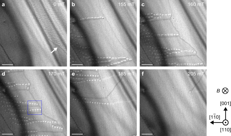
Topological defects embedded in or combined with domain walls have been proposed in various systems, some of which are referred to as domain wall skyrmions or domain wall bimerons. However, the experimental observation of such topological defects remains an ongoing challenge. Here, using Lorentz transmission electron microscopy, we report the experimental discovery of domain wall bimerons in chiral magnet Co-Zn-Mn(110) thin films. By applying a magnetic field, multidomain structures develop, and simultaneously, chained or isolated bimerons arise as the localized state between the domains with the opposite in-plane components of net magnetization. The multidomain formation is attributed to magnetic anisotropy and dipolar interaction, and domain wall bimerons are stabilized by the Dzyaloshinskii-Moriya interaction. In addition, micromagnetic simulations show that domain wall bimerons appear for a wide range of conditions in chiral magnets with cubic magnetic anisotropy. Our results promote further study in various fields of physics.


Conflict of interest statement

The authors declare no competing interests.

Figures

Fig. 1
Fig. 1. Schematic of DWs and skyrmions, and the corresponding LTEM images.
a Magnetic structure of DWs in ferromagnets. b, c Corresponding LTEM images of DWs for underfocused (b) and overfocused (c) conditions. d Magnetic structure of skyrmions. e, f Corresponding LTEM images of skyrmions for underfocused (e) and overfocused (f) conditions.
Fig. 2
Fig. 2. Development of magnetic structures in the Co8.5Zn7.5Mn4(110) thin film with t ~50 nm.
A series of underfocused LTEM images (defocus value Δf = −2 mm) obtained at 330 K and 0 mT (a), 155 mT (b), 160 mT (c), 170 mT (d), 185 mT (e), and 205 mT (f). The magnetic field was applied perpendicular to the thin film plane. The scale bars are 1 μm. The strong dark line contrasts (the so-called bend contours) seen in the upper left to lower middle of each figure appear at locations where the Bragg condition is locally satisfied due to sample bending. Further details are displayed in Supplementary Figs. 1, 2. The blue dotted box in d corresponds to Fig. 3a.
Fig. 3
Fig. 3. Magnetic structure of DW bimerons and isolated DW bimerons.
a, b Underfocused (Δf  = −1.5 mm) (a) and overfocused (Δf = +1.5 mm) (b) LTEM images, enlarged view of the blue dotted box in Fig. 2d. The scale bars are 500 nm. c Magnetic flux density (magnetization) map obtained using the transport of intensity equation analysis based on a and b. The scale bar is 500 nm. The color wheel (inset) represents the orientation and magnitude of the in-plane component of magnetic flux density. The in-plane magnetizations on both sides of the bimeron chains have the opposite directions along the in-plane <110> directions, verifying the existence of DW bimerons. d, e Schematic illustration of DW (d) and DW bimerons (e). The arrows depict perpendicularly averaged magnetization to the plane. In the domains, average magnetization are oriented in the <100> directions of the magnetic easy axes. f Underfocused LTEM image with Δf = −2 mm obtained at 324 K and 190 mT. g Enlarged view of the blue dotted box in f.
Fig. 4
Fig. 4. Micromagnetic and LTEM image simulations of DW bimerons in a cubic chiral magnet (110) thin film with t = 50 nm.
a Simulated results of magnetization distributions for various cubic magnetocrystalline anisotropy (Kc) and magnetic fields (B). Parameters are as follows: saturation magnetization Msat = 180 kA/m, exchange stiffness constant A = 3.83 pJ/m and DMI constant D = 0.332 mJ/m2. K0 = D2/4 A and Bd = D2/2MsatA are normalization constants. The magnetic easy axes are the <100> directions (Kc > 0). The size of each image is 1.6 × 1.6 μm2. The color wheel (upper right panel) represents the orientation and magnitude of perpendicularly averaged in-plane components of truncated in-plane conical magnetization to the plane. The white and black indicate +z and −z directions, respectively. b Enlarged view of magnetic structure corresponding to magenta dotted box in a. c Calculated TCD map for b. d, e Simulated underfocused (Δf = −1.5 mm) (d) and overfocused (Δf = +1.5 mm) (e) LTEM images for b. Further details are shown in Supplementary Fig. 4.

References

    1. Chuang I, et al. Cosmology in the laboratory: defect dynamics in liquid crystals. Science. 1991;251:1336. doi: 10.1126/science.251.4999.1336. - DOI - PubMed
    1. Lahiri J, et al. An extended defect in graphene as a metallic wire. Nat. Nanotechnol. 2010;5:326–329. doi: 10.1038/nnano.2010.53. - DOI - PubMed
    1. Parkin SSP, et al. Magnetic domain-wall racetrack memory. Science. 2008;320:190. doi: 10.1126/science.1145799. - DOI - PubMed
    1. Catalan G, et al. Domain wall nanoelectronics. Rev. Mod. Phys. 2012;84:119. doi: 10.1103/RevModPhys.84.119. - DOI
    1. Yasuda K, et al. Quantized chiral edge conduction on domain walls of a magnetic topological insulator. Science. 2017;358:1311–1314. doi: 10.1126/science.aan5991. - DOI - PubMed