. 2020 Oct 21:128:10.1063/5.0024019.
doi: 10.1063/5.0024019.

Interfacial spin-orbit torques

Affiliations

Interfacial spin-orbit torques

V P Amin et al. J Appl Phys. .

Abstract

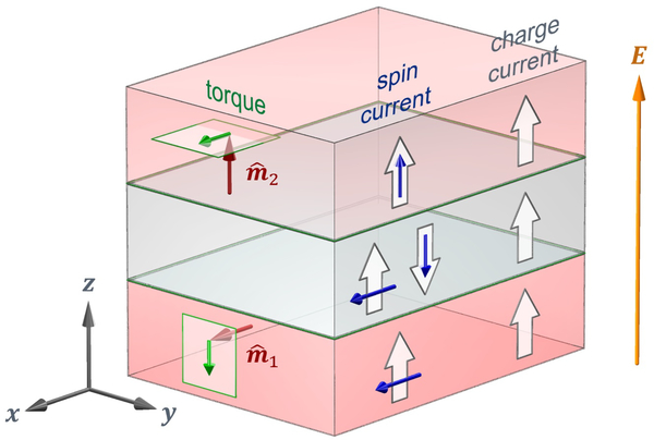
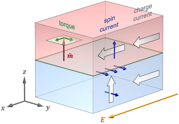
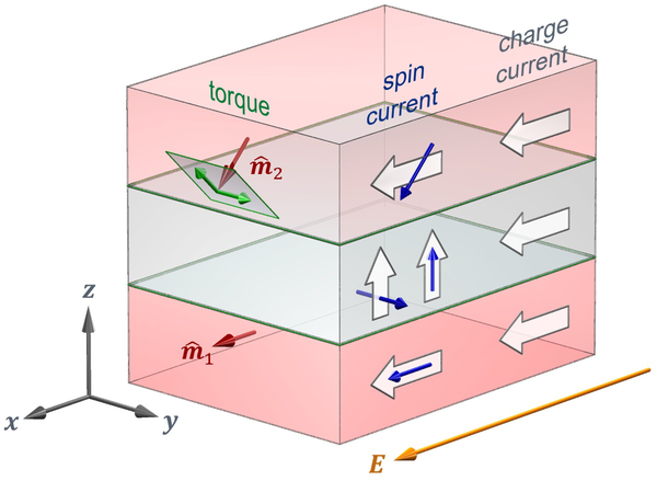
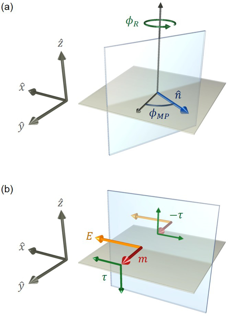
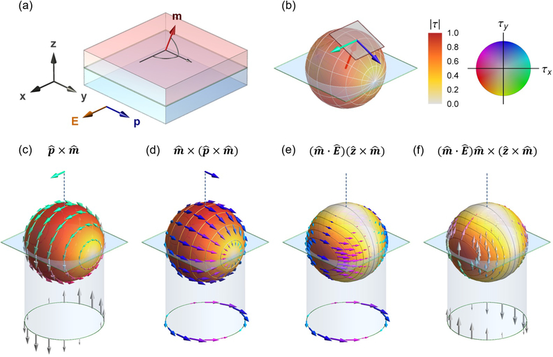
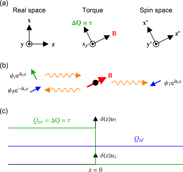
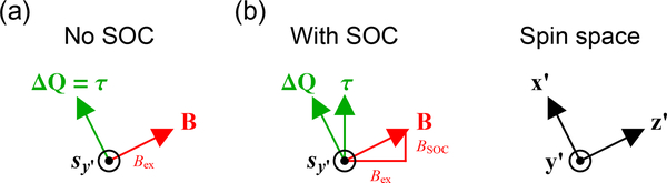
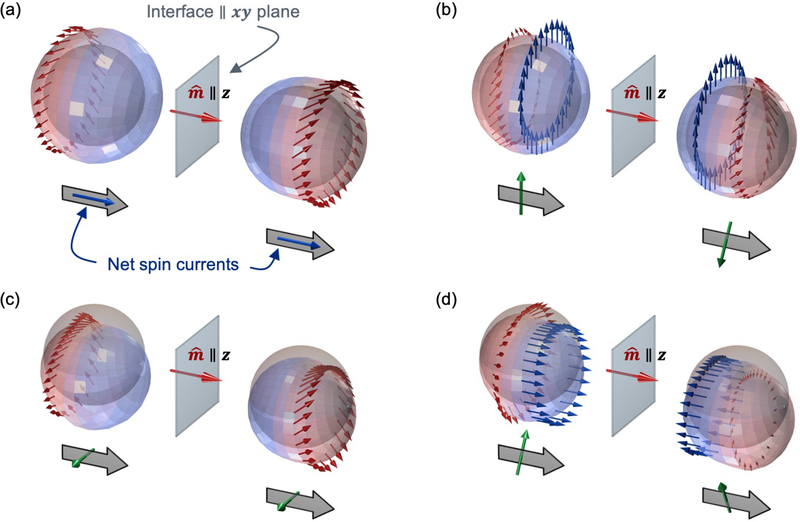
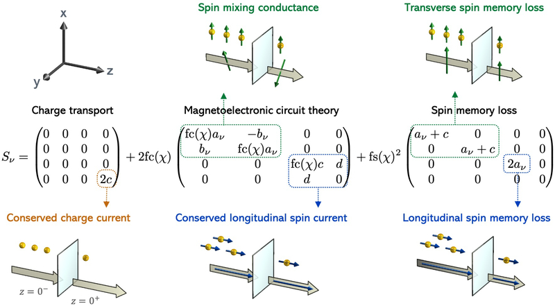
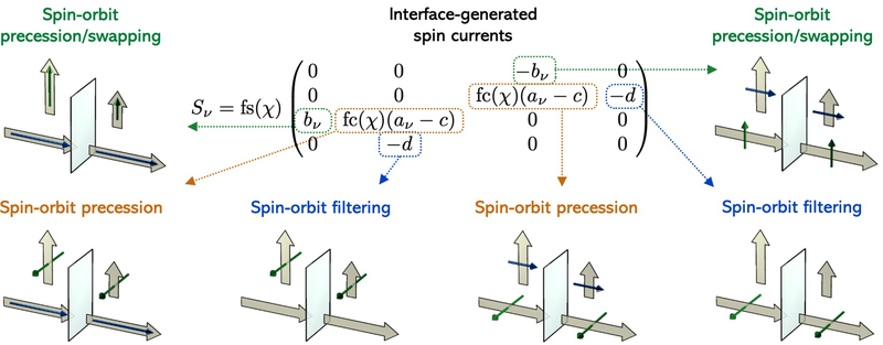
Spin-orbit torques offer a promising mechanism for electrically controlling magnetization dynamics in nanoscale heterostructures. While spin-orbit torques occur predominately at interfaces, the physical mechanisms underlying these torques can originate in both the bulk layers and at interfaces. Classifying spin-orbit torques based on the region that they originate in provides clues as to how to optimize the effect. While most bulk spin-orbit torque contributions are well studied, many of the interfacial contributions allowed by symmetry have yet to be fully explored theoretically and experimentally. To facilitate progress, we review interfacial spin-orbit torques from a semiclassical viewpoint and relate these contributions to recent experimental results. Within the same model, we show the relationship between different interface transport parameters. For charges and spins flowing perpendicular to the interface, interfacial spin-orbit coupling both modifies the mixing conductance of magnetoelectronic circuit theory and gives rise to spin memory loss. For in-plane electric fields, interfacial spin-orbit coupling gives rise to torques described by spin-orbit filtering, spin swapping and precession. In addition, these same interfacial processes generate spin currents that flow into the non-magnetic layer. For in-plane electric fields in trilayer structures, the spin currents generated at the interface between one ferromagnetic layer and the non-magnetic spacer layer can propagate through the non-magnetic layer to produce novel torques on the other ferromagnetic layer.


Figures

FIG. 15.
FIG. 15.
Visual representation of the relationship between the angles χ/, the barrier strengths u/, and the scaled z-velocity kz*=kz/kF. In the limit that u = 0 and u → ∞, χ = π/2 and χ → 0.
FIG. 1.
FIG. 1.
Magnetic tunnel junctions (dark red arrows represent magnetization direction). (a) Standard magnetic tunnel junction with fixed and free layers and the control current following the same path as the read current. (b) magnetic tunnel junction grown on heavy metal layer with separate read and control current paths.
FIG. 2.
FIG. 2.
Schematic of different angular momentum reservoirs and the interactions coupling them. In ferromagnetic metals, the net magnetization is the sum of the magnetic moments of electrons carrying both orbital and spin angular momentum, with the latter dominating in transition metal ferromagnets. The magnetic exchange potential couples the spin angular momentum of the magnetization to the spin angular momentum of the carriers. The spin-orbit interaction couples the spin angular momentum of the carriers to their orbital angular momentum. The crystal field potential couples the orbital angular momentum of carriers to the angular momentum of the atomic lattice. Spin-orbit torques arise when an applied electric field promotes angular momentum transfer from the atomic lattice to the magnetization using carriers as mediators for the transfer.
FIG. 3.
FIG. 3.
Magnetic trilayer and perpendicular transport. The top and bottom ferromagnetic layers are separated by a nonmagnetic layer. In each layer, the charge current flows along the electric field, where flow directions are given as block arrows. In each ferromagnetic layer, the spin current flows along the charge current with spins aligned with the magnetization (red arrows). For spin currents, block arrows indicate electron flow direction and blue arrows indicate spin direction. Equivalently, block arrows could also indicate charge flow direction with blue arrows indicating magnetic moment. In the non-magnetic layer, the spins in the spin current are a combination of spins aligned with the lower layer magnetization and anti-aligned with the upper layer magnetization (here given by x^z^). In the absence of spin-orbit coupling, the spin current with spin direction longitudinal to the magnetization is conserved across the interfaces. Note that spin currents are unchanged by flipping both the flow and spin directions. The discontinuity in the spin current at the interfaces, given by the spin direction transverse to the magnetization, is the spin transfer torque, indicated for the top and bottom layers by the green arrows. Typically, one layer will be able to respond to the torques and the other layer will be essentially fixed though one of several mechanisms.
FIG. 4.
FIG. 4.
Magnetic bilayer and in-plane transport. In both the top ferromagnetic layer and bottom non-magnetic layer, charge currents flow along the electric field, where flow directions are given as block arrows. In the ferromagnetic layer, the spin current flows along the charge current with spins aligned with the magnetization (red arrow), where for spin currents block arrows give flow direction and blue arrows give spin direction. Green arrows indicate the two components of the torque on the magnetization. In the bottom nonmagnetic layer, the spin Hall effect generates a spin current with flow along z^ and spin direction along y^. In the absence of spin-orbit coupling at the interface, the discontinuity of the spin Hall current across the interface gives the interfacial contribution to spin-orbit torque on the magnetization. However, with nonvanishing interfacial spin-orbit coupling, the Rashba-Edelstein effect generates a spin accumulation at the interface that exerts an exchange torque on the magnetization. As will be discussed throughout this review article, additional torques arise from spin-orbit scattering at the interface (not shown here), possibly contributing to torques measured in experiments.
FIG. 5.
FIG. 5.
Real and reciprocal space depictions of the Rashba-Edelstein effect. Carriers are restricted to an idealized two-dimensional interface. (a) The carriers feel an effective magnetic field along u(k)=k×z^ (green arrow) due to spin-orbit coupling. (b) The band structure obtained from the Rashba Hamiltonian in Eq. 2 for vanishing exchange interaction (Δ = 0). The spin expectation values (arrows) are shown at the Fermi energy EF, where EF > E(k = 0). (c) The Fermi surface forms two circular sheets distinguished by their spin expectation values being parallel (outer circle) or antiparallel (inner circle) to u(k). An electric field biases carrier occupations, where blue arrows indicate increased occupation and red decreased, leading to a net spin polarization along E×z^.
FIG. 6.
FIG. 6.
Real and reciprocal space depictions of the role of interfacial spin-orbit coupling. In all panels, green arrows indicate the effective magnetic field along u(k)=k×z^ due to spin-orbit coupling. In panels (a) and (c), red and blue arrows indicate spin directions. In panels (b) and (d), colors indicate the change in occupation of the associated states due to the in-plane electric field, blue increased occupation, purple no change, and red decreased. (a) Unpolarized carriers scattering from the interfacial spin-orbit field become spin-polarized (spin-orbit filtering) because the field creates a spin-dependent potential barrier. (b) Spin polarization after transmission through the interface for unpolarized incoming carriers on a circular slice (constant kz) of one sheet of the Fermi surface. The non-equilibrium occupation due to the electric field leads to a net flow of transmitted electrons along z^ with a net spin polarization along z^×E. (c) In ferromagnetic layers, carriers are spin-polarized along the magnetization. Scattering from the interface, these spins precess around u(k) (spin-orbit precession). (d) In-plane spin polarization after transmission through the interface for incoming carriers polarized along z^ on a circular slice (constant kz) of one sheet of the Fermi surface. The non-equilibrium occupation due to the electric field leads to the transmitted spins carrying a net spin flow along z^ with net spin polarization along m^×(z^×E).
FIG. 7.
FIG. 7.
Magnetic trilayer and in-plane transport. The top and bottom ferromagnetic layers are separated by a non-magnetic layer. In each layer, the current flows along the electric field, where flow directions are given as block arrows. In the ferromagnetic layers, the spin currents shown here flow along the charge currents with spins aligned with the magnetization (indicated by red arrows). Note that for spin currents, block arrows give flow direction and blue arrows give spin direction. Green arrows indicate the two components of the torque on the magnetization. In the non-magnetic layer, spin currents originating in the lower ferromagnetic layers and flowing out-of-plane (z^) have spin directions along both y^ and z^ (other contributions to the spin current are not shown). The spin currents with y-spin direction can arise from the spin Hall effect in any layer or through the spin-orbit filtering effect at interfaces. The spin currents with z-spin direction are not allowed by symmetry in bulk nonmagnets; these spin currents can only arise in the ferromagnetic layers through various processes or at the interfaces through the spin-orbit precession effect. Spin transfer torques arising from the spin currents with z-spin direction could switch ferromagnetic layers with perpendicular magnetic anisotropy, suggesting applications of possible technological interest.
FIG. 8.
FIG. 8.
Depiction of symmetries and their consequences in a polycrystalline bilayer. (a) For nonmagnetic bilayers, any rotation φR about the out-of-plane direction (z-axis) leaves the system unchanged. Likewise, any mirror-plane transformation where the mirror-plane normal lies in-plane (parameterized by the angle 𝜙MP) also leaves the system invariant. (b) Under an applied, in-plane electric field E, all symmetries are broken except the mirror-plane that lies parallel to the electric field, since the electric field is a polar vector. If one layer is ferromagnetic, this symmetry is broken unless the magnetization m^ points normal to the mirror-plane, since magnetization is a pseudovector. In this configuration, the torque τ must vanish, because a nonvanishing torque reflected through the mirror-plane will reverse, violating the system’s symmetry.
FIG. 9.
FIG. 9.
(a) Depiction of a bilayer consisting of a heavy metal layer (blue region) and a ferromagnetic layer (red region) under an applied, in-plane electric field E (here along x^). The high symmetry direction p=z^×E^ is normal to the x/z mirror-plane, where z^ points out-of-plane. (b) Spin-orbit torque is conveniently defined using two basis vectors: dampinglike (m^×(p×m^)) and fieldlike (p×m^), which are defined relative to the high-symmetry direction p. These basis vectors span the plane perpendicular to the magnetization and vanish when m^p, satisfying the bilayer’s symmetry constraints. However, the dampinglike and fieldlike basis vectors are not sufficient to describe the magnetization-dependence of spin-orbit torque unless they have magnetization-dependent coefficients. The full expansion of spin-orbit torque using constant coefficients is more complicated, and is given by Eq. 6. This expansion consists of four-vector functions of the magnetization, depicted in (c)-(f). Each vector function can be additionally multiplied by any power of mz2. The in-plane and out-of-plane torques are projected below and above the unit sphere respectively. The full expansion suggests that if measurements of in-plane and out-of-plane torques are interpreted as arising from only dampinglike or fieldlike torques, the full magnetization dependence may be misrepresented. For example, when m^z^, measuring a small torque component pointing along p indicates a small dampinglike torque, but this measurement could be incorrectly interpreted as weak potential for magnetization switching, because the torque component (m^E)z^×m^ shown in (e) is zero at m^z^ but contributes to the switching process for other magnetization directions.
FIG. 10.
FIG. 10.
Schematic of an electron scattering off of an infinitely strong magnetic impurity. (a) Coordinate systems for real space and spin space, where transport occurs along z and the impurity’s magnetic moment points along z′. The basis states |↑〉 and |↓〉 correspond to spins along ±z′. (b) In the limit that B → ∞, the impurity perfectly reflects ↑ spins and perfectly transmits ↓ spins. Thus, for an incoming spin state ψI ∝ |↑〉+|↓〉 along x′ (transverse to the impurity’s magnetic moment), the reflected and transmitted spin states point along ±z′ (parallel or antiparallel to the impurity’s magnetic moment) (c) Plot of the spin current as a function of position. The incoming state carries spin current Qzx; the indices indicate flow along z and spin direction along x′. The reflected and transmitted states each carry the same spin current Qzz; the indices indicate flow along z and spin direction along z′. Thus, the net change in spin current across the impurity is Qzx, indicating that the incoming spin angular momentum is completely absorbed. The absorption of spin current results in a torque on the impurity’s magnetic moment.
FIG. 11.
FIG. 11.
Result of adding spin-orbit coupling to the magnetic impurity. (a) Without spin-orbit coupling, the magnetic field of the impurity B equals the exchange field Bex. The absorbed spin current ΔQ equals the torque τs × Bex. (b) With spin-orbit coupling, B is the sum of the exchange field Bex and the spin-orbit field Bsoc. The absorbed spin current is perpendicular to the total field, not the exchange field. However, only the part of the absorbed spin current that is perpendicular to the exchange field contributes to the torque on the magnetization. The rest of the absorbed spin current exerts a torque on the lattice through the spin-orbit coupling.
FIG. 12.
FIG. 12.
Plots depicting the nonequilibrium distribution functions gα(0±, k) in the presence of interfacial spin-orbit scattering. Each picture illustrates the physics captured by a single matrix element in the matrices defined in Eq. 33 or Eq. 38. The interfacial exchange field (red arrow) points out-of-plane (along z). The gray sphere represents the equilibrium Fermi surface. The colored surfaces represent the nonequilibrium perturbation to the Fermi surface, given by the charge distribution gc(0±, k). The arrows depict the spin distribution function gi(0±, k) for i ∈ [x, y, z] for particular contours over the Fermi surface (which have constant polar scattering angle). Blue and red regions represent the incoming and outgoing (scattered) carriers respectively. The net spin current at z = 0± is shown below the distribution functions, where the block arrows denote spin flow (always out-of-plane) and the tubular arrows denote spin direction. Note that we use transverse and longitudinal to denote spin directions relative to the interfacial exchange field. (a) Scenario where the incident carriers have two different charge accumulations but no spin accumulation. Regardless, the scattered carriers are spin polarized from their interaction with the interfacial exchange and spin-orbit fields. The net spin currents after scattering have longitudinal spin directions and are conserved across the interface. (b) Scenario where the incident carriers have two different transverse spin accumulations. The net spin currents after scattering also have transverse spin directions but are rotated relative to the spin accumulation and not conserved across the interface. (c) Scenario where two different in-plane charge currents flow at z = 0±, indicated by differing shifts the Fermi surface. The scattered carriers become spin polarized and the net out-of-plane spin currents have transverse spin direction. (d) Scenario where two different in-plane, longitudinal spin currents flow at z = 0±. The net out-of-plane spin currents have transverse spin direction and are not conserved across the interface.
FIG. 13.
FIG. 13.
Breakdown of the Sν matrices (ν ∈ [i-r, t]) when spin or charge accumulations drive transport at interfaces. The matrix St determines the spin and charge accumulation μ at the interface (see Eq. 28). The symmetric response S¯=Sir+St determines the average spin current j¯z at the interface (see Eq. 29). The antisymmetric response ΔS = Si-rSt determines the difference in spin current Δjz across the interface (see Eq. 30). The matrix column specifies the spin and charge accumulations at z = 0± while the row gives the components of μ, j¯z, or Δjz, depending on whether Eq. 28, Eq. 29, or Eq. 30 is used. The images depict the charge accumulations (gold spheres) or the spin accumulations (gold spheres with arrows) that drive the system and the resulting spin currents at z = 0±, where block arrows denote flow direction and tubular arrows denote spin direction.
FIG. 14.
FIG. 14.
Breakdown of the Sν matrices when in-plane spin/charge currents drive transport at interfaces. As in Fig. 13, the matrix St determines the spin/charge accumulation μ at the interface (see Eq. 28), the symmetric response S¯=Sir+St determines the average spin current j¯z at the interface (see Eq. 29), and the antisymmetric response ΔS = Si-rSt determines the difference in spin current Δjz across the interface (see Eq. 30). The column specifies the in-plane spin/charge currents at z = 0± while the row gives the components of μ, j¯z, or Δjz, depending on whether Eq. 28, Eq. 29, or Eq. 30 is used. The images depict both the in-plane and out-of-plane spin currents at z = 0± using block arrows for flow direction and tubular arrows for spin direction.

References

    1. Apalkov D, Dieny B, and Slaughter J, Proceedings of the IEEE 104, 1796 (2016).
    1. Hanyu T, Endoh T, Suzuki D, Koike H, Ma Y, Onizawa N, Natsui M, Ikeda S, and Ohno H, Proceedings of the IEEE 104, 1844 (2016).
    1. Butler W, Zhang X-G, Schulthess T, and MacLaren J, Physical Review B 63, 054416 (2001).
    1. Parkin SS, Kaiser C, Panchula A, Rice PM, Hughes B, Samant M, and Yang S-H, Nature materials 3, 862 (2004). - PubMed
    1. Yuasa S, Nagahama T, Fukushima A, Suzuki Y, and Ando K, Nature materials 3, 868 (2004). - PubMed

LinkOut - more resources