

Electrochemical Nozaki-Hiyama-Kishi Coupling: Scope, Applications, and Mechanism
- PMID: 34128671
- PMCID: PMC8720499
- DOI: 10.1021/jacs.1c03007
Electrochemical Nozaki-Hiyama-Kishi Coupling: Scope, Applications, and Mechanism
Abstract
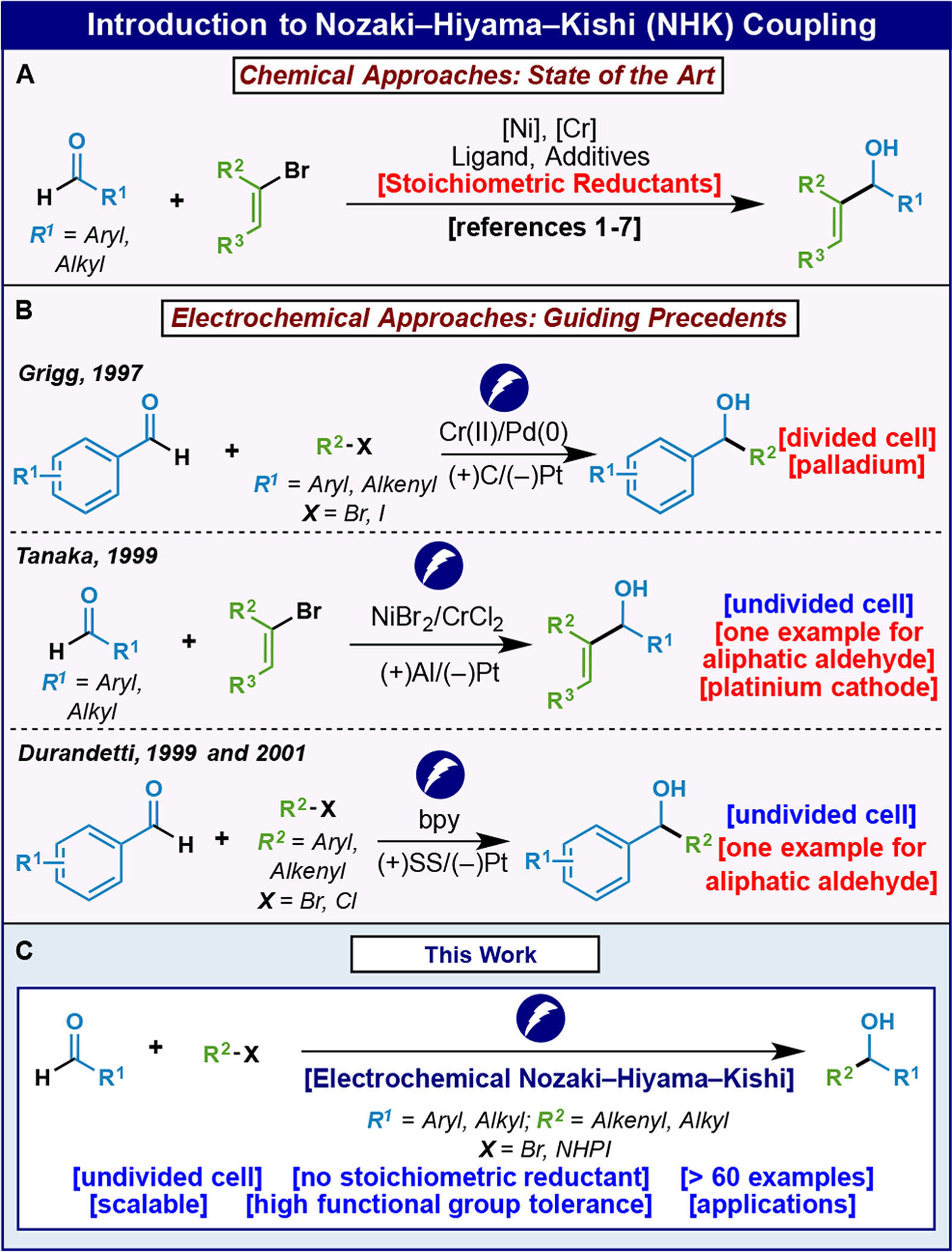
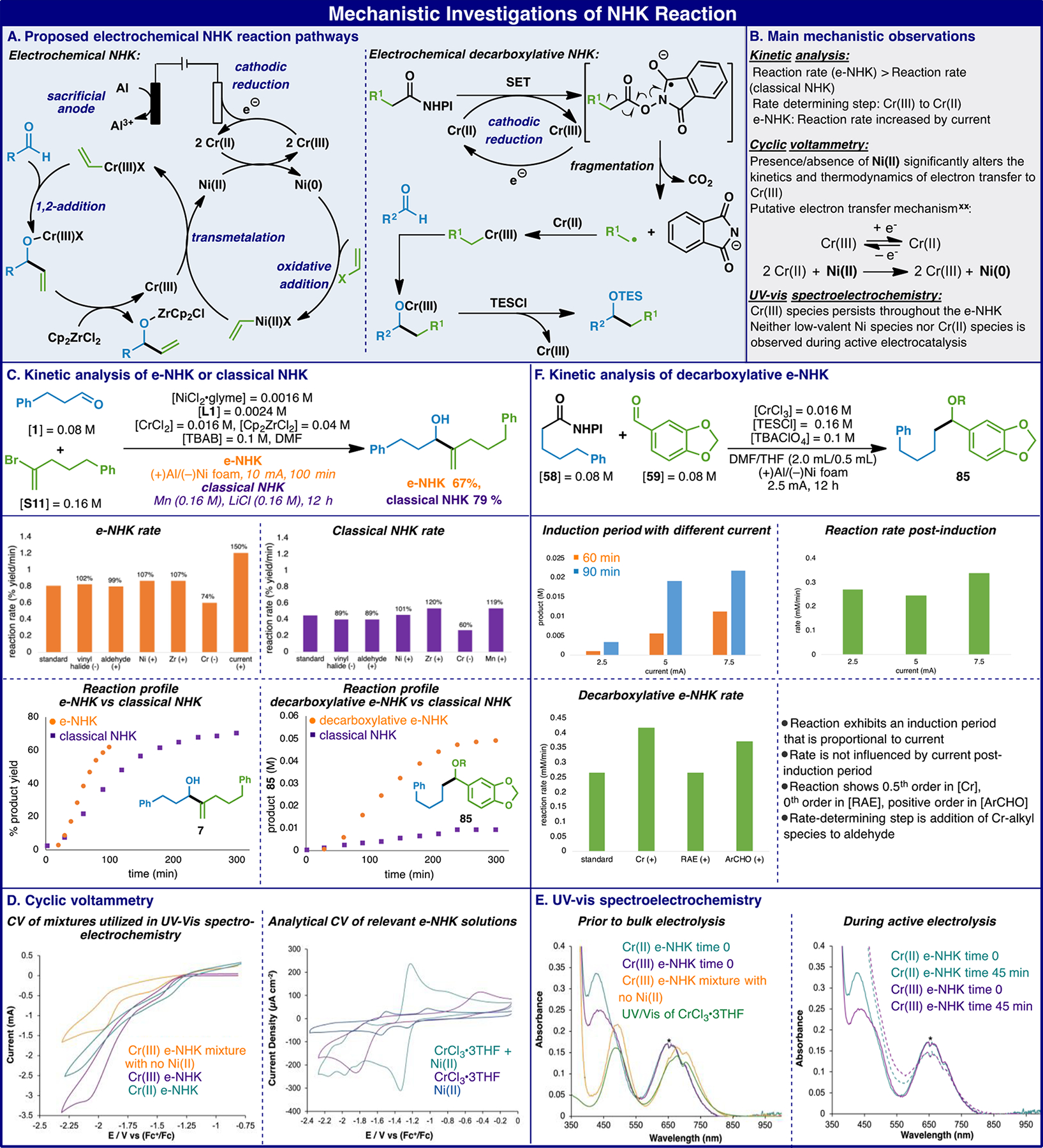
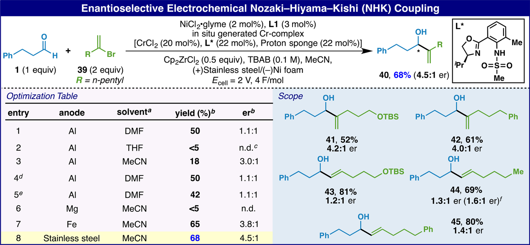
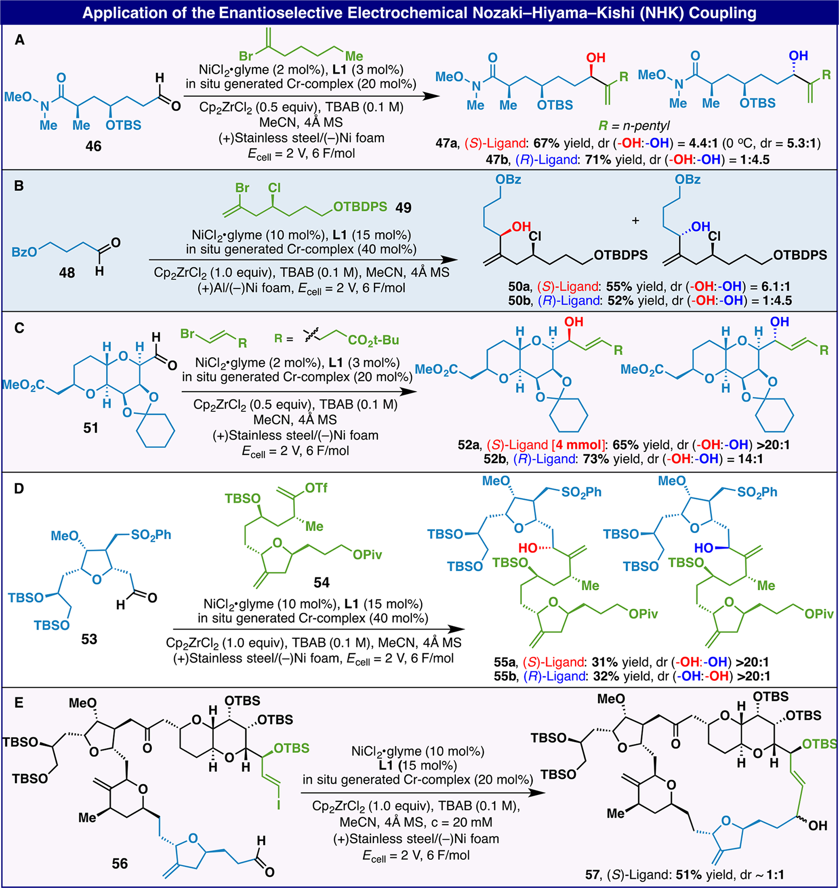
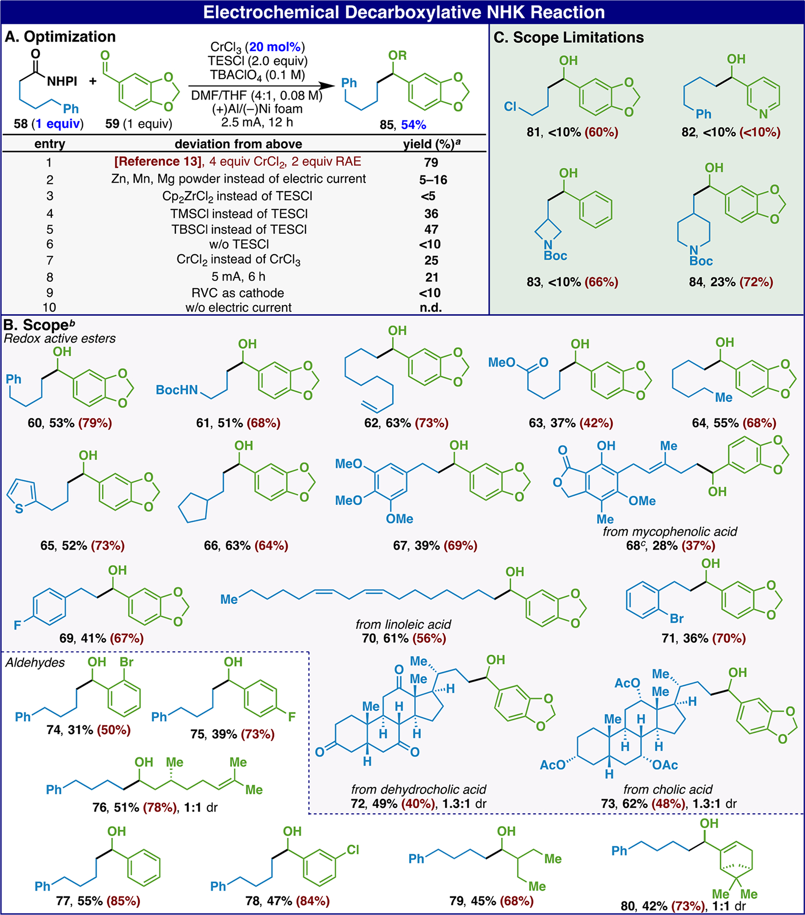
One of the most oft-employed methods for C-C bond formation involving the coupling of vinyl-halides with aldehydes catalyzed by Ni and Cr (Nozaki-Hiyama-Kishi, NHK) has been rendered more practical using an electroreductive manifold. Although early studies pointed to the feasibility of such a process, those precedents were never applied by others due to cumbersome setups and limited scope. Here we show that a carefully optimized electroreductive procedure can enable a more sustainable approach to NHK, even in an asymmetric fashion on highly complex medicinally relevant systems. The e-NHK can even enable non-canonical substrate classes, such as redox-active esters, to participate with low loadings of Cr when conventional chemical techniques fail. A combination of detailed kinetics, cyclic voltammetry, and in situ UV-vis spectroelectrochemistry of these processes illuminates the subtle features of this mechanistically intricate process.
Figures
Similar articles
-
Chromium- and Metal-Reductant-Free Asymmetric Nozaki-Hiyama-Kishi (NHK) Reaction Enabled by Metallaphotoredox Catalysis.Angew Chem Int Ed Engl. 2024 Sep 9;63(37):e202408195. doi: 10.1002/anie.202408195. Epub 2024 Aug 8. Angew Chem Int Ed Engl. 2024. PMID: 38923245
-
An electrochemical coupling of organic halide with aldehydes, catalytic in chromium and nickel salts. the Nozaki-Hiyama-Kishi reaction.Org Lett. 2001 Jun 28;3(13):2073-6. doi: 10.1021/ol016033g. Org Lett. 2001. PMID: 11418052
-
Cr/Ni-catalyzed vinylation of aldehydes: a mechanistic study on the catalytic roles of nickel and chromium.Chemistry. 2011 Apr 18;17(17):4765-73. doi: 10.1002/chem.201003366. Epub 2011 Mar 21. Chemistry. 2011. PMID: 21425369
-
Electrocatalytic Asymmetric Nozaki-Hiyama-Kishi Decarboxylative Coupling: Scope, Applications, and Mechanism.J Am Chem Soc. 2024 Feb 21;146(7):4872-4882. doi: 10.1021/jacs.3c13442. Epub 2024 Feb 7. J Am Chem Soc. 2024. PMID: 38324710 Free PMC article.
-
Organocatalysed asymmetric Mannich reactions.Chem Soc Rev. 2008 Jan;37(1):29-41. doi: 10.1039/b713885g. Epub 2007 Oct 30. Chem Soc Rev. 2008. PMID: 18197331 Review.
Cited by
-
Unlocking Chromium Decarboxylative Ligand-to-Metal Charge Transfer: Efficient and Redox-Neutral Allylation of Aldehydes Using Carboxylic Acids.J Am Chem Soc. 2025 Jul 2;147(26):22759-22767. doi: 10.1021/jacs.5c04691. Epub 2025 Jun 16. J Am Chem Soc. 2025. PMID: 40518937 Free PMC article.
-
Electronic Structures of Nickel(II)-Bis(indanyloxazoline)-dihalide Catalysts: Understanding Ligand Field Contributions That Promote C(sp2)-C(sp3) Cross-Coupling.Inorg Chem. 2023 Aug 28;62(34):14010-14027. doi: 10.1021/acs.inorgchem.3c02048. Epub 2023 Aug 16. Inorg Chem. 2023. PMID: 37584501 Free PMC article.
-
A review of recent advances in electrochemical and photoelectrochemical late-stage functionalization classified by anodic oxidation, cathodic reduction, and paired electrolysis.Beilstein J Org Chem. 2024 Oct 9;20:2500-2566. doi: 10.3762/bjoc.20.214. eCollection 2024. Beilstein J Org Chem. 2024. PMID: 39403305 Free PMC article. Review.
-
Deep Electroreductive Chemistry: Harnessing Carbon- and Silicon-based Reactive Intermediates in Organic Synthesis.ACS Catal. 2023 Jun 16;13(12):8038-8048. doi: 10.1021/acscatal.3c01174. Epub 2023 May 31. ACS Catal. 2023. PMID: 38707967 Free PMC article.
-
Metal-free photocatalytic cross-electrophile coupling enables C1 homologation and alkylation of carboxylic acids with aldehydes.Nat Commun. 2024 Feb 19;15(1):1509. doi: 10.1038/s41467-024-45804-z. Nat Commun. 2024. PMID: 38374079 Free PMC article.
References
-
- Okude Y; Hirano S; Hiyama T; Nozaki H Grignard-Type Carbonyl Addition of Allyl Halides by Means of Chromous Salt. A Chemospecific Synthesis of Homoallyl Alcohols. J. Am. Chem. Soc 1977, 99, 3179–3181.
-
- Jin H; Uenishi J; Christ WJ; Kishi Y Catalytic Effect of Nickel(II) Chloride and Palladium(II) Acetate on Chromium(II)-Mediated Coupling Reaction of Iodo Olefins with Aldehydes. J. Am. Chem. Soc 1986, 108, 5644–5646.
- Takai K; Tagashira M; Kuroda T; Oshima K; Utimoto K; Nozaki H Reactions of Alkenylchromium Reagents Prepared from Alkenyl Trifluoromethanesulfonates (Triflates) with Chromium(II) Chloride under Nickel Catalysis. J. Am. Chem. Soc 1986, 108, 6048–6050. - PubMed
-
-
For selected reviews, see:
- rstner A Carbon − Carbon Bond Formations Involving Organochromium(III) Reagents. Chem. Rev 1999, 99, 991–1045. - PubMed
- Avalos M; Babiano R; Cintas P; Jimenez JL; Palacios JC Synthetic Variations Based on Low-Valent Chromium: New Developments. Chem. Soc. Rev 1999, 28, 169–177.
- Wessjohann LA; Scheid G Recent Advances in Chromium(II)- and Chromium(III)-Mediated Organic Synthesis. Synthesis 1999, 1999, 1–36.
- Lumbroso A; Cooke ML; Breit B Catalytic Asymmetric Synthesis of Allylic Alcohols and Derivatives and Their Applications in Organic Synthesis. Angew. Chem., Int. Ed 2013, 52, 1890–1932. - PubMed
- Takai K Addition of Organochromium Reagents to Carbonyl Compounds. Org. React 2004, 253–612.
- Takai K Organochromium Reagents. In Comprehensive Organic Synthesis, 2nd ed.; Knochel P, Molander GA, Eds.; Elsevier Science: Oxford, U.K., 2014; Vol. 1, pp 159–203.
- Hargaden GC; Guiry PJ The Development of the Asymmetric Nozaki–Hiyama–Kishi Reaction. Adv. Synth. Catal 2007, 349, 2407–2424.
- Tian Q; Zhang G Recent Advances in the Asymmetric Nozaki–Hiyama–Kishi Reaction. Synthesis 2016, 48, 4038–4049.
- Gil A; Albericio F; Álvarez M Role of the Nozaki–Hiyama–Takai–Kishi Reaction in the Synthesis of Natural Products. Chem. Rev 2017, 117, 8420–8446. - PubMed
-
-
- Kochi JK; Davis DD Reduction of Organic Halides by Chromium(II). Mechanism of the Formation of Benzylchromium Ion. J. Am. Chem. Soc 1964, 86, 5264–5271.
-
- Fürstner A; Shi N A Multicomponent Redox System Accounts for the First Nozaki–Hiyama–Kishi Reactions Catalytic in Chromium. J. Am. Chem. Soc 1996, 118, 2533–2534.
- Fürstner A; Shi N Nozaki–Hiyama–Kishi Reactions Catalytic in Chromium. J. Am. Chem. Soc 1996, 118, 12349–12357.
- Kuroboshi M; Tanaka M; Kishimoto S; Goto K; Tanaka H; Torii S Ni/Cr/Al Multi-Metal Redox-Mediated Alkenylation of Aldehydes. Tetrahedron Lett 1999, 40, 2785–2788.
Publication types
MeSH terms
Substances
Grants and funding
LinkOut - more resources
Full Text Sources
Other Literature Sources
