

Hybrid Fluoroscopic and Neurophysiological Targeting of Responsive Neurostimulation of the Rolandic Cortex
- PMID: 34133746
- PMCID: PMC12312620
- DOI: 10.1093/ons/opab182
Hybrid Fluoroscopic and Neurophysiological Targeting of Responsive Neurostimulation of the Rolandic Cortex
Abstract
Background: Precise targeting of cortical surface electrodes to epileptogenic regions defined by anatomic and electrophysiological guideposts remains a surgical challenge during implantation of responsive neurostimulation (RNS) devices.
Objective: To describe a hybrid fluoroscopic and neurophysiological technique for targeting of subdural cortical surface electrodes to anatomic regions with limited direct visualization, such as the interhemispheric fissure.
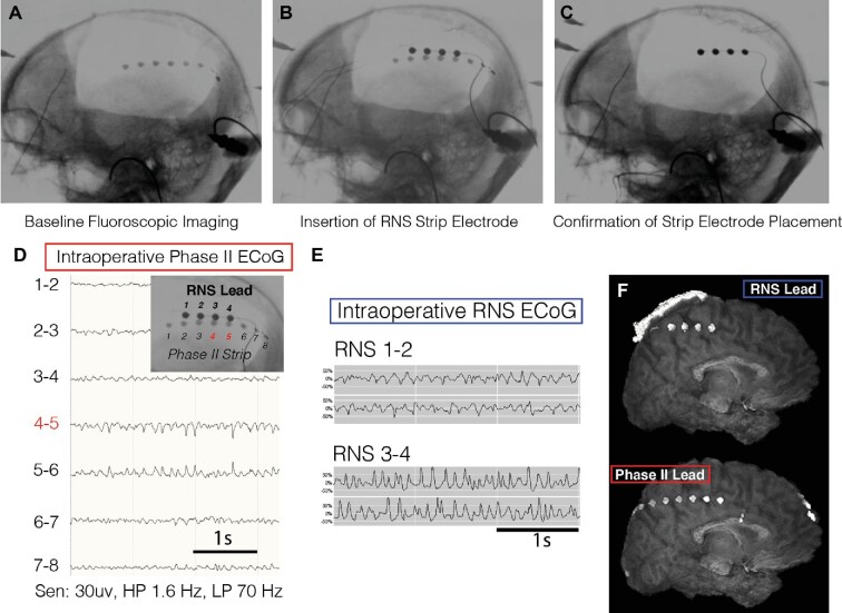
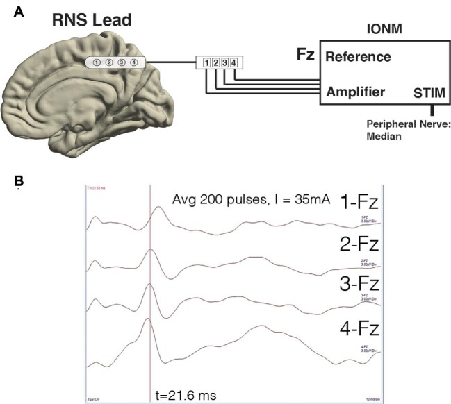
Methods: Intraoperative two-dimensional (2D) fluoroscopy was used to colocalize and align an electrode for permanent device implantation with a temporary in Situ electrode placed for extraoperative seizure mapping. Intraoperative phase reversal mapping technique was performed to distinguish primary somatosensory and motor cortex.
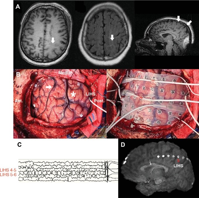
Results: We applied these techniques to optimize placement of an interhemispheric strip electrode connected to a responsive neurostimulator system for detection and treatment of seizures arising from a large perirolandic cortical malformation. Intraoperative neuromonitoring (IONM) phase reversal technique facilitated neuroanatomic mapping and electrode placement.
Conclusion: In challenging-to-access anatomic regions, fluoroscopy and intraoperative neurophysiology can be employed to augment targeting of neuromodulation electrodes to the site of seizure onset zone or specific neurophysiological biomarkers of clinical interest while minimizing brain retraction.
Keywords: Cortical electrode; Epilepsy; Fluoroscopy; Physiological mapping; RNS.
© Congress of Neurological Surgeons 2021.
Figures
Similar articles
-
Deep brain and cortical stimulation for epilepsy.Cochrane Database Syst Rev. 2017 Jul 18;7(7):CD008497. doi: 10.1002/14651858.CD008497.pub3. Cochrane Database Syst Rev. 2017. PMID: 28718878 Free PMC article.
-
Deep brain and cortical stimulation for epilepsy.Cochrane Database Syst Rev. 2014 Jun 17;(6):CD008497. doi: 10.1002/14651858.CD008497.pub2. Cochrane Database Syst Rev. 2014. Update in: Cochrane Database Syst Rev. 2017 Jul 18;7:CD008497. doi: 10.1002/14651858.CD008497.pub3. PMID: 24937707 Updated.
-
Intraoperative Neuromonitoring for the Lower-Extremity Region Using Motor-Evoked Potential With Direct Cortical Stimulation in Brain Tumor Surgeries.J Clin Neurophysiol. 2025 Mar 1;42(3):272-278. doi: 10.1097/WNP.0000000000001108. Epub 2024 Aug 2. J Clin Neurophysiol. 2025. PMID: 39090797
-
Idiopathic (Genetic) Generalized Epilepsy.2024 Feb 12. In: StatPearls [Internet]. Treasure Island (FL): StatPearls Publishing; 2025 Jan–. 2024 Feb 12. In: StatPearls [Internet]. Treasure Island (FL): StatPearls Publishing; 2025 Jan–. PMID: 31536218 Free Books & Documents.
-
Quantification of Subdural Electrode Shift Between Initial Implantation, Postimplantation Computed Tomography, and Subsequent Resection Surgery.Oper Neurosurg. 2019 Jan 1;16(1):9-19. doi: 10.1093/ons/opy050. Oper Neurosurg. 2019. PMID: 29617890 Free PMC article.
References
-
- Tate MC, Guo L, McEvoy J, Chang EF. Safety and efficacy of motor mapping utilizing short pulse train direct cortical stimulation. Stereotact Funct Neurosurg. 2013;91(6):379-385. - PubMed
-
- Breshears JD, Molinaro AM, Chang EF. A probabilistic map of the human ventral sensorimotor cortex using electrical stimulation. J Neurosurg. 2015;123(2):340-349. - PubMed
-
- Byrne RW, Sanai N, Landeiro JA, Duffau H. Introduction: advances in intraoperative brain mapping. Neurosurg Focus. 2018;45(VideoSuppl2):Intro. - PubMed
-
- Muh CR, Chou ND, Rahimpour S, et al. Cortical stimulation mapping for localization of visual and auditory language in pediatric epilepsy patients. J Neurosurg Pediatr. 2019;25(2):1-10. - PubMed
-
- Han SJ, Teton Z, Gupta K, Kawamoto A, Raslan AM. Novel use of stimulating fence-post technique for functional mapping of subcortical white matter during tumor resection: a technical case series. Oper Neurosurg. 2020;30(20):2559. - PubMed
MeSH terms
Grants and funding
LinkOut - more resources
Full Text Sources
