Review
. 2019 Sep 4;11(1):71.
doi: 10.1007/s40820-019-0302-0.

Graphene Nanostructure-Based Tactile Sensors for Electronic Skin Applications

Affiliations
Review

Graphene Nanostructure-Based Tactile Sensors for Electronic Skin Applications

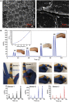
Pei Miao et al. Nanomicro Lett. .

Abstract

Skin is the largest organ of the human body and can perceive and respond to complex environmental stimulations. Recently, the development of electronic skin (E-skin) for the mimicry of the human sensory system has drawn great attention due to its potential applications in wearable human health monitoring and care systems, advanced robotics, artificial intelligence, and human-machine interfaces. Tactile sense is one of the most important senses of human skin that has attracted special attention. The ability to obtain unique functions using diverse assembly processible methods has rapidly advanced the use of graphene, the most celebrated two-dimensional material, in electronic tactile sensing devices. With a special emphasis on the works achieved since 2016, this review begins with the assembly and modification of graphene materials and then critically and comprehensively summarizes the most advanced material assembly methods, device construction technologies and signal characterization approaches in pressure and strain detection based on graphene and its derivative materials. This review emphasizes on: (1) the underlying working principles of these types of sensors and the unique roles and advantages of graphene materials; (2) state-of-the-art protocols recently developed for high-performance tactile sensing, including representative examples; and (3) perspectives and current challenges for graphene-based tactile sensors in E-skin applications. A summary of these cutting-edge developments intends to provide readers with a deep understanding of the future design of high-quality tactile sensing devices and paves a path for their future commercial applications in the field of E-skin.

Keywords: Assembly; Electronic skin; Graphene derivatives; Tactile sensor.


Figures

Fig. 1
Fig. 1
Typical capacitance-type tactile sensors with graphene as electrodes. a Schematic diagram of the fabrication processes for different conformal graphene electrodes and SEM images of three kinds of graphene films derived from PMMA-based, ultraviolet-curable adhesive-mediated, and microconformal transfer methods. b Illustration of a capacitive pressure sensor based on MGrE, a schematic diagram of the sensing mechanisms and grasping with the proposed pressure sensor. Reproduced with permission from Ref. [42]. Copyright 2019 American Chemical Society
Fig. 2
Fig. 2
Typical crosstalk-free, multipoint recognition of flexible, and transparent capacitive graphene-based tactile sensors. a Schematic illustration of the sensor array composed of graphene-patterned top and bottom PET layers, PDMS insulator, and SU-8 spacers. b Schematic illustration of the 3 × 3 tactile cell array and the finite element analysis result for deflection of the top layer under 8 kPa applied to the center of cell-O. Reproduced with permission from Ref. [52]. Copyright 2017 WILEY–VCH Verlag GmbH & Co. KGaA, Weinheim. c Schematic diagram illustrating the concept of a graphene-based capacitive sensor. The sensor consists of three layers. The top and bottom layers are composed of patterned graphene electrodes on a PET film substrate. d Optical images of stretchable devices mounted on a palm for remote controlling the toy car. Inset of each image shows relative capacitance changes for spread (left) and grip (right) statuses of the hand. Reproduced with permission from Ref. [53]. Copyright 2017 American Chemical Society
Fig. 3
Fig. 3
Versatile graphene and its derivatives are used to fabricate multifunctional capacitance-type tactile sensors. a Schematic diagram showing the four pixels (2 × 2) of the multimodal E-skin sensor, which were capable of mapping three individual stimuli including humidity, temperature and pressure. b Black-and-white maps of the calculated sensitivities of the three sensors during the finger pressing event (top), and a 2D color map of the distributions of the corresponding temperatures (blue), humidity (red), and pressures (green). Reproduced with permission from Ref. [54]. Copyright 2016 WILEY–VCH Verlag GmbH & Co. KGaA, Weinheim. c Schematic of the loading–unloading cycle for the pressure sensor with GO foam as a dielectric material. d Transient response to the placement and removal of several ultrasmall weights in the GO foam-based sensor. Inset: a petal on the sensor. e The pressure response to the strawberry. Insert: Bird’s eye view of the strawberry standing on the sensor arrays. Reproduced with permission from Ref. [56]. Copyright 2016 Elsevier Ltd
Fig. 4
Fig. 4
Typical 1D graphene architectures used for piezoresistive pressure sensors. a Photograph of a graphene fiber with a PDMS support. b SEM image of the cross-sectional view of a graphene/PDMS hollow tubing after Ni removal. Reproduced with permission from Ref. [46]. Copyright 2017 Elsevier Ltd. c FESEM image of the randomly stacked electrospun nanofibers. d Schematic showing the pressure response measurement of the sensor in bending and response curves when bent to a radius of 180 µm for different substrate thicknesses. e Tested pressure response of the device in the bent state and the response of the device fabricated on a 1.4-µm-thick PET substrate for bending radii from 15 to 80 µm for different normal forces. f Photograph of an integrated sensor array attached to the surface of a soft balloon, to which a pressure was applied by a pinching motion (top panel). Measured pressure data distribution under complex bending, showing no pressure signal from deformation, such as wrinkling (bottom panel). Reproduced with permission from Ref. [47]. Copyright 2016 Macmillan Publishers Limited
Fig. 5
Fig. 5
2D graphene films obtained by CVD used for piezoresistive pressure sensors. a Schematic illustration of the fabrication procedure of a tactile sensor composed of 2D graphene films and a PET substrate. Reproduced with permission from Ref. [62]. Copyright 2018 Springer Science + Business Media, LLC, part of Springer Nature. b Optical photograph of an ultrathin, transparent and flexible tactile sensor. Inset: The geometric dimension of the sensor. c Sensitivity of the device to longitudinal displacement at different axial distances of 5, 10, 15, and 20 mm. Reproduced with permission from Ref. [58]. Copyright 2017 The Royal Society of Chemistry
Fig. 6
Fig. 6
Modification and microstructure of CVD 2D graphene can further improve sensing performance of the devices. a Schematic representation of the plasma surface modification of a graphene sheet by NH3/Ar plasma. Nitrogen atoms are expected to substitute the carbon atoms in the form of pyridinic-N, pyrrolic-N, and graphitic-N configurations. b Relative change in resistance upon applied tensile strain for the fabricated sensors using the untreated graphene and plasma-treated graphene sheet. Reproduced with permission from Ref. [64]. Copyright 2017 American Chemical Society. c An optical image of the boundary between the single-layer graphene channel and the graphene flake thin-film electrode. Inset: Optical image of the entire device. d The resistance changes with tensile strain from 0 to 20%. The gauge factor is estimated at 42.2 for x-directional strain and 71.4 for y-directional strain with a rough linear fit. Insets show the schematics of force and measurement directions. Reproduced with permission from Ref. [65]. Copyright 2017 The Elsevier Ltd
Fig. 7
Fig. 7
2D graphene films obtained by a solution fabrication process and used for piezoresistive pressure sensors. a The generated and enlarged scaled cracks under minor strain (left). The magnified SEM image of generated and enlarged scaled cracks under minor strain (right). b The strain sensor can meet the demands of subtle, large and complex human motion monitoring. Reproduced with permission from Ref. [69]. Copyright 2018 The Royal Society of Chemistry
Fig. 8
Fig. 8
Schematic of the fabrication procedures of a 3D graphene material with a sponge as a template. a Preparation route for RGO/PU (or PVC) sponges and their multidimensional sensor applications. Reproduced with permission from Ref. [74]. Copyright 2017 Elsevier Ltd. b The fabrication procedures of the flexible tactile sensor array using PU as a template. Reproduced with permission from Ref. [76]. Copyright 2018 IEEE
Fig. 9
Fig. 9
The mechanism and application of 3D graphene materials with sponges as template-based tactile sensors. a SEM images of the MWCNT/RGO@PU-5C sponges with nanogaps, microcracks and fractured skeletons (The top panel). Schematic of the MWNT-RGO flake-wrapped PU foam with the magnified image of its individual skeleton at three stages, without pressure, at low pressure, and at high pressure (The bottom panel). Reproduced with permission from Ref. [77]. Copyright 2018 The Royal Society of Chemistry. b Real-time response of the MWNT-RGO@PU piezoresistive sensor for various small-scale motion monitoring applications was studied using the throat while pronouncing different words. Reproduced with permission from Ref. [73]. Copyright 2017 Wiley–VCH Verlag GmbH & Co. KGaA
Fig. 10
Fig. 10
Typical paradigms for 3D graphene materials with paper as the template used for tactile sensing. a Tissue paper with RGO. b SEM photo of the tissue paper sensor at high magnification. c Applications for various intense motion detections. Reproduced with permission from Ref. [78]. Copyright 2017 American Chemical Society
Fig. 11
Fig. 11
3D graphene materials with other polymer porous materials as templates used for tactile sensing. a Photograph of both electrodes on a brachioradialis muscle and on biceps brachii muscle for electromyogram measurement. Reproduced with permission from Ref. [88]. Copyright 2017 WILEY–VCH Verlag GmbH & Co. KGaA, Weinheim. b Experimental setup of the tuning fork vibration test and a schematic of the test circuit for the graphene film/PDMS sensor. c Photo of the piezoelectric ceramic transducer test. Reproduced with permission from Ref. [92]. Copyright 2017 AIP Publishing
Fig. 12
Fig. 12
3D graphene materials with metal porous materials as templates used for tactile sensing. a Schematic process for fabricating pressure and strain sensors with the graphene porous network structure. b Signal variations in relative resistance corresponding to different walking/bending states and wrist blood pressure. Reproduced with permission from Ref. [85]. Copyright 2016 American Chemical Society
Fig. 13
Fig. 13
Typical 3D graphene structures via surfactant-assisted self-assembly used for tactile sensors. a Schematic illustration of the fabrication process of 3D microporous polystyrene/graphene aerogels. Reproduced with permission from Ref. [103]. Copyright 2016 Wiley–VCH Verlag GmbH & Co. KGaA, Weinheim. b Illustrations of the preparation of a sparkling graphene block. c Photograph of a sparkling graphene block bent to 180° (left) and real-time images from a high-speed camera showing that the sparkling graphene block can rapidly bounce a steel ball. Reproduced with permission from Ref. [102]. Copyright 2017 American Chemical Society. d The as-fabricated tactile sensor as a promising candidate for wearable devices. Reproduced with permission from Ref. [103]. Copyright 2016 Wiley–VCH Verlag GmbH & Co. KGaA, Weinheim
Fig. 14
Fig. 14
A novel method to obtain 3D graphene structures by using high-internal-phase emulsion (HIPE) as a template. a Schematic illustration of the procedure for fabricating the RGO@PolyHIPE foams via HIPE polymerization, optical microscopy images, and SEM images of the foam. b Relative change in the sensor’s current and pressure curves. The inset shows the relative current change in a small pressure range below 140 Pa (left). Comparison of the detection limit of minimum pressure and the responsive pressure range between the sensor described in the current work and previously reported sensors (right). Reproduced with permission from Ref. [106]. Copyright 2019 American Chemical Society
Fig. 15
Fig. 15
Bioinspired hierarchical graphene structures as active layers for pressure detection. a SEM image of hierarchically structured graphene/PDMS array. Inset is a magnified image of an individual structure. Platinum sputtering was omitted prior to the SEM imaging; a clear SEM image implies that the sample surface was fully covered with conducting graphene. Reproduced with permission from Ref. [109]. Copyright 2016 WILEY–VCH Verlag GmbH & Co. KGaA, Weinheim. b Photographs (insets) and optical micrographs of the RGO coating on PDMS after exposure to a high temperature. Reproduced with permission from Ref. [111]. Copyright 2018 American Chemical Society. c Picture of a human hand and partial enlargement (inset), and the schematic diagram of sandwich ultrasensitive pressure sensors based on the skin-like wrinkle film (top panel). SEM images showing the morphology of a skin-like wrinkle film (bottom panel). Reproduced with permission from Ref. [112]. Copyright 2018 The Royal Society of Chemistry. d Schematic illustration showing the structure of the 3D graphene film containing a continuous graphene film and closely packed concentric hexagonal graphene nanoribbon rings. Picture of a fingertip and its fingerprint. In addition, SEM image of a 3D graphene film on a SiO2/Si substrate. Reproduced with permission from Ref. [113]. Copyright 2018 Springer
Fig. 16
Fig. 16
Microstructures inspired from animal and plant organs provide interesting ideas for the preparation of active materials for graphene-based tactile sensors. a Comparison of the surface topographies between a Shar-Pei dog’s skin and RGO crumples by using Canny edge detection. b Continuum surgical robots with the as-fabricated pressure sensor for the collision-aware the transoral robotic surgery procedure. Reproduced with permission from Ref. [116]. Copyright 2019 American Chemical Society
Fig. 17
Fig. 17
Graphene combined with inorganic functional materials to enhance the sensing performance of piezoresistive devices. a SEM images at different magnifications of a graphene-amorphous carbon hierarchical foam and graphene foam. b Five ultralight graphene-amorphous carbon hierarchical foam pieces with sizes of 20 × 20 × 3 mm3 stacked on the corolla of dandelion, and different simulated stress dispersion statuses of graphene foam and graphene-amorphous carbon hierarchical foam tube walls under the same line load. Reproduced with permission from Ref. [123]. Copyright 2017 American Chemical Society
Fig. 18
Fig. 18
Typical paradigms concerning graphene combined with polymers to enhance the sensing performance of piezoresistive devices. a Schematic illustration of the mechanism for the formation of PVDF fibers coated by RGO nanosheets, followed by electrostatic interactions. b Top view of the metal letters “C,” “A” and “S” positioned over the pressure sensor array and the current map of pressure distributions. c Photograph of the device loaded on two wrists for testing blood pressure through near-surface arteries. Reproduced with permission from Ref. [128]. Copyright 2016 Elsevier Ltd. d The multifunctional E-skins attached on a hand, wrist and throat to monitor biosignals. Reproduced with permission from Ref. [50]. Copyright 2017 Elsevier Ltd.
Fig. 19
Fig. 19
A representative graphene/polymer tactile sensor obtained by taking advantage of the amphiphilicity of GO. a Schematic of the fabrication of a flexible piezoresistive sensor. b Various practical applications, including a biomonitoring capability, loading tiny objects, and monitoring various human movement behaviors. Reproduced with permission from Ref. [135]. Copyright 2018 WILEY–VCH Verlag GmbH & Co. KGaA, Weinheim
Fig. 20
Fig. 20
A representative graphene tactile sensors based on FET devices. a Schematic images of pressure-sensitive graphene FETs with air-dielectric layers before and after folding. The air-dielectric layer is placed between the graphene channel and the gate electrode, as illustrated in the schematic image (inset). b Schematic illustrations for the pressure-sensing mechanism using an air-dielectric graphene FET. Reproduced with permission from Ref. [45]. Copyright 2017 Macmillan Publishers Limited. c Integration of a graphene/MoS2 device with a smartphone to acquire and transfer the electronic data of human motion by Bluetooth communication. Reproduced with permission from Ref. [140]. Copyright 2018 WILEY–VCH Verlag GmbH & Co. KGaA, Weinheim
Fig. 21
Fig. 21
High-performance sensing devices by combining a FET with a triboelectric nanogenerator. a Schematic diagram of the graphene tribotronic device. b Characterization of the graphene tribotronic touch sensor. Reproduced with permission from Ref. [146]. Copyright 2016 WILEY–VCH Verlag GmbH & Co. KGaA, Weinheim. c Energy band diagram of the tribotronic GFET device in contact with poly(tetrafluoroethylene) and Cu. Reproduced with permission from Ref. [145]. Copyright 2018 American Chemical Society

References

    1. Chen S, Jiang K, Lou Z, Chen D, Shen G. Recent developments in graphene-based tactile sensors and e-skins. Adv. Mater. Technol. 2018;3(2):1700248. doi: 10.1002/admt.201700248. - DOI
    1. Huang L, Santiago D, Loyselle P, Dai L. Graphene-based nanomaterials for flexible and wearable supercapacitors. Small. 2018;14(43):e1800879. doi: 10.1002/smll.201800879. - DOI - PubMed
    1. Liu Y, Weiss NO, Duan X, Cheng H-C, Huang Y, Duan X. Van der waals heterostructures and devices. Nat. Rev. Mater. 2016;1(9):16042. doi: 10.1038/natrevmats.2016.42. - DOI
    1. Wang C, Xia K, Wang H, Liang X, Yin Z, Zhang Y. Advanced carbon for flexible and wearable electronics. Adv. Mater. 2019;31(9):e1801072. doi: 10.1002/adma.201801072. - DOI - PubMed
    1. Wen L, Li F, Cheng HM. Carbon nanotubes and graphene for flexible electrochemical energy storage: from materials to devices. Adv. Mater. 2016;28(22):4306–4337. doi: 10.1002/adma.201504225. - DOI - PubMed

LinkOut - more resources