Review
. 2020 Oct 29;13(1):13.
doi: 10.1007/s40820-020-00522-1.

DFT-Guided Design and Fabrication of Carbon-Nitride-Based Materials for Energy Storage Devices: A Review

Affiliations
Review

DFT-Guided Design and Fabrication of Carbon-Nitride-Based Materials for Energy Storage Devices: A Review

David Adekoya et al. Nanomicro Lett. .

Abstract

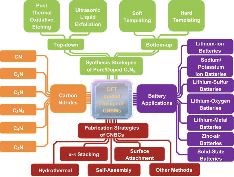
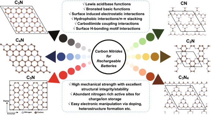
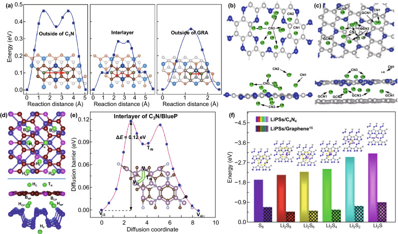
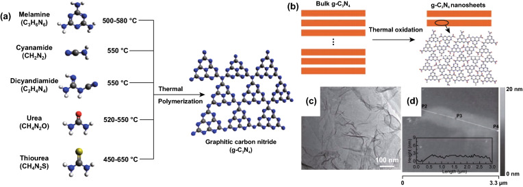
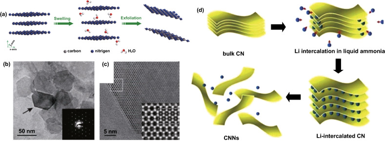
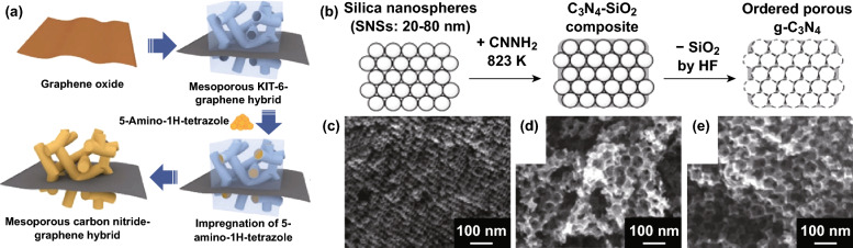
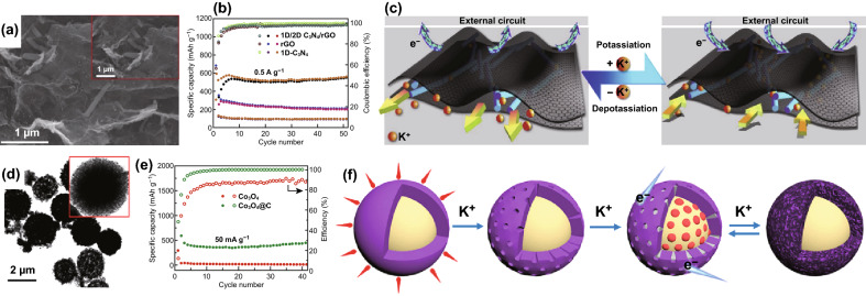
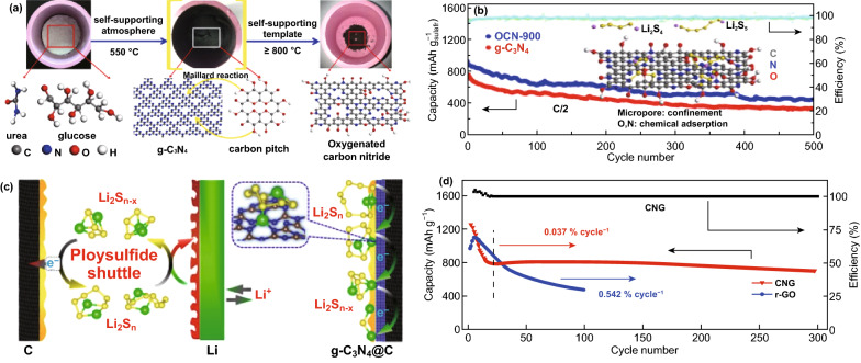
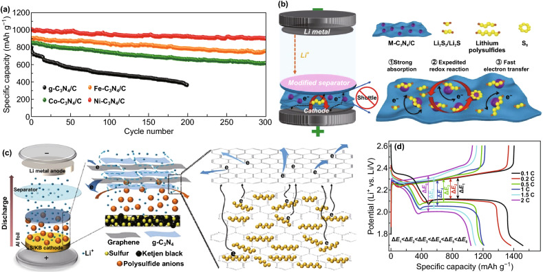
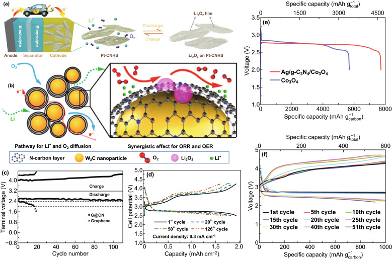
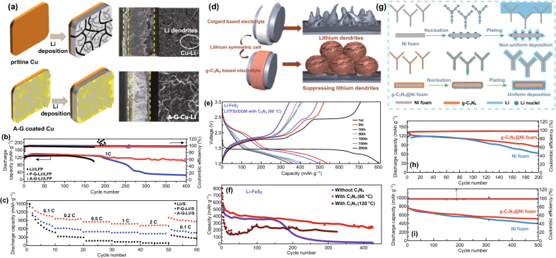
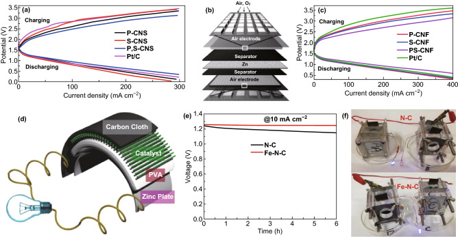
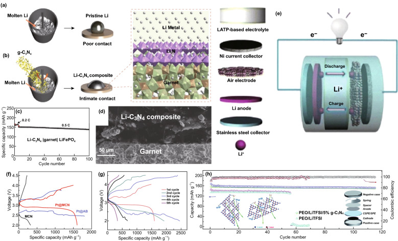
Carbon nitrides (including CN, C2N, C3N, C3N4, C4N, and C5N) are a unique family of nitrogen-rich carbon materials with multiple beneficial properties in crystalline structures, morphologies, and electronic configurations. In this review, we provide a comprehensive review on these materials properties, theoretical advantages, the synthesis and modification strategies of different carbon nitride-based materials (CNBMs) and their application in existing and emerging rechargeable battery systems, such as lithium-ion batteries, sodium and potassium-ion batteries, lithium sulfur batteries, lithium oxygen batteries, lithium metal batteries, zinc-ion batteries, and solid-state batteries. The central theme of this review is to apply the theoretical and computational design to guide the experimental synthesis of CNBMs for energy storage, i.e., facilitate the application of first-principle studies and density functional theory for electrode material design, synthesis, and characterization of different CNBMs for the aforementioned rechargeable batteries. At last, we conclude with the challenges, and prospects of CNBMs, and propose future perspectives and strategies for further advancement of CNBMs for rechargeable batteries.

Keywords: Anode; Carbon nitrides; Density functional theory; Metal-ion batteries; g-C3N4.


Figures

Fig. 1
Fig. 1
Overview of the main topics of this work, including DFT-guided design (symbolized by the “CPU” at the center), the molecular configuration of carbon nitrides (yellow block), the synthesis strategies of pure/doped carbon nitrides (green block), the fabrication strategies of CNBCs (red block) and the battery applications of CNBMs (purple block). (Color figure online)
Fig. 2
Fig. 2
Common forms of nitrogen species in nitrogen-doped carbon materials. Reproduced with permission from Ref. [12]. Copyright permissions from Wiley–VCH. (Color figure online)
Fig. 3
Fig. 3
Geometric structures of the pyridinic and graphitic-N-based carbon nitrides reported for rechargeable batteries and their surface functionalities. The brown spheres represent carbon atoms, and the light blue one represents nitrogen atoms in the 2D carbon nitrides structures. (Color figure online)
Fig. 4
Fig. 4
a Top view and side view of the supercell (2 × 2) g-C3N3. b Band structure and total density of state for 1 × 1 g-C3N3. Reproduced with permission from Ref. [15]. c Relaxed structure of 2  ×  2 C2N monolayer, H1, H2, and H3 are possible binding sites for transition metal atom doping on the C2N. d Band structure and density of states of C2N monolayer. Reproduced with permission from Ref. [28]. e Schematic structure of monolayer g-C3N4. Reproduced with permission from Ref. [18]. f Calculated band structures of monolayer g-C3N4 with planar or buckled topology. Reproduced with permission from Ref. [20]. g Optimized structure and h band structure of C3N monolayer. The unit cell is shown by the red dashed line. Reproduced with permission from Ref. [29]. i Top and side view of the atomic structure of monolayer C4N. The black dashed lines show the 3 × 3 × 1 supercell of monolayer C4N. Four adsorption sites were considered (H1, H2, TC, TN). j Electronic band structures and k PDOS of the unit cell of a pristine C4N monolayer. Reproduced with permission from Ref. [30]. l Top (upper) and side (lower) view of the atomic structure of C5N monolayer. The gray and blue balls represent C atoms and N atoms, respectively. m Band structure and n density of states (DOS) of C5N monolayer obtained from HSE06 calculations. The black, red, and blue lines denote the total DOS of C5N, the partial DOS of C atoms, and the partial DOS of N atoms, respectively. Reproduced with permission from Ref. [27]. Copyright permissions from Elsevier, Royal Society of Chemistry and Wiley–VCH. (Color figure online)
Fig. 5
Fig. 5
a Optimized atomic structure of S-doped mesoporous CN (S-MCN). b Charge density profile of S-MCN, blue color—lowest electron density (0%), and red color—highest electron density (100%). Reproduced with permission from Ref. [31]. c Optimized structure g-C3N4 monolayer, showing possible P-doping sites. d DOS plots of P-doped g-C3N4 for P substitution at N1 and N2 sites. Reproduced with permission from Ref. [32]. Copyright permissions from American Chemical Society and Springer Nature. (Color figure online)
Fig. 6
Fig. 6
Electrochemical properties of carbon nitrides can be predicted from DFT calculations. Reproduced with permission from [, –40]. Copyright permissions from Elsevier, American Chemical Society, Wiley–VCH, and IOP Publishing. (Color figure online)
Fig. 7
Fig. 7
Reversible Li active sites in a 2D-C3N4 sheet, and b 1D-C3N4 fiber. Green means reversible Li atoms and red means non-reversible Li atoms. c Top and side view of stable intercalation structures of n Li ions into C3N. Reproduced with permission from Ref. [40]. d Diffusion paths and e corresponding energy barriers of Li migration in C3N-S2. Reproduced with permission from Ref. [51]. f Binding energy of Li2S4/Li2S6/Li2S8 interacting with G, BN, C2N, C3N4 and DOL/DME solvent, respectively. Reproduced with permission from Ref. [17]. g Isosurfaces of charge density difference of Li2S, Li2S2, Li2S4, Li2S6, Li2S8, and S8 adsorbed on the surface of C5N with the isovalue of 0.003 A−3. Blue wireframes denote loss of electrons and yellow wireframes denote gain of electrons. Reproduced with permission from Ref. [27]. Copyright permissions from American Chemical Society, Elsevier and Wiley–VCH. (Color figure online)
Fig. 8
Fig. 8
a Energy barrier for Na diffusion through g-C3N4, b corresponding Na diffusion path. c Energy barriers for Na diffusion through P-g-C3N4, d corresponding Na diffusion path. Reproduced with permission from Ref. [32]. e Adsorption energies of LiPSs on transition metal embedded C2N monolayers. f Adsorption energies of long-chain LiPSs with transition metal embedded C2N, 1,2-dimethoxyethane (DME) and 1,3-dioxolane (DOL). Reproduced with permission from Ref. [28]. Copyright permissions from Springer Nature and Elsevier. (Color figure online)
Fig. 9
Fig. 9
a Energy profiles for Li atom diffusion on C3N/GRA, along with the corresponding pathways denoted as red arrows. Carbon atoms from graphene—gray balls, carbon atoms from C3N—orange balls, nitrogen atoms—blue and lithium atoms—green. Reproduced with permission from Ref. [37]. b Top and side views of Li13–C2N structure; c top and side views of the Li11–C2N/graphene bilayer. Different adsorption sites are indicated as CN1, CN2, CN3, GCN1, GCN2, and GCN3 for both structures. Reproduced with permission from Ref. [38]. d Top and side views of the Li adsorption site on the C3N/P heterostructure (Li/C3N/P, C3N/Li/P, and C3N/P/Li). HC and TN sites are on the outer surface of C3N, and HP site is on the outer surface of phosphorene, HCP, HNP, BCP, and BNP sites are in the interlayer of the C3N/P heterostructure. Reproduced with permission from Ref. [64]. e Lithium migration pathway and corresponding energy profile through Path II of the interlayer of C3N/Blue P heterostructure. Reproduced with permission from Ref. [65]. f Adsorption energy for S8 cluster and LiPSs on C4N4 monolayer (bars without patterns) and graphene (bars with patterns), respectively. The insets on the pillars show S8 or Li2Sn/C4N4 structures generated by the principle of minimum energy. Reproduced with permission from Ref. [56]. Copyright permissions from Elsevier, American Chemical Society and Royal Society of Chemistry. (Color figure online)
Fig. 10
Fig. 10
a Schematic illustration of one of the top-down synthesis approach (thermal polymerization) for g-C3N4 using different precursors. Black balls—carbon (C), blue balls—nitrogen (N), white balls—hydrogen (H), red balls—oxygen (O), and yellow balls—sulfur (S), respectively. Reproduced with permission from Ref. [84]. b Schematic of the synthesis of g-C3N4 nanosheets from bulk g-C3N4. In the atomic model, carbon atoms—gray balls, nitrogen atoms—blue balls and hydrogen atoms—red. c TEM image of g-C3N4 nanosheets. d Tapping-mode AFM image of a single g-C3N4 nanosheet deposited on the silicon wafer substrate. The inset is the height curve determined along the line between P1 and P4. Reproduced with permission from Ref. [88]. Copyright permissions from American Chemical Society and Wiley–VCH. (Color figure online)
Fig. 11
Fig. 11
a Schematic illustration of liquid-exfoliation process from bulk g-C3N4 to ultrathin nanosheets. Reproduced with permission from Ref. [90]. b TEM image of exfoliated ultrathin nanosheets, c higher magnification of a carbon nitride nanosheet edge viewed along [001]. Reproduced with permission from Ref. [91] d Schematic diagram of the lithiation and exfoliation of g-C3N4 nanosheets from bulk g-C3N4. Reproduced with permission from Ref. [92]. Copyright permissions from American Chemical Society. (Color figure online)
Fig. 12
Fig. 12
a Schematic representation of the synthesis protocol for synthesizing the mesoporous C3N5 and its graphene hybrid. Reproduced with permission from Ref. [98]. b Schematic illustration of the synthesis of ordered porous g-C3N4 by using close-packed silica nanospheres (SNSs) as the primary template. ce FE-SEM images of porous g-C3N4 at different resolutions. Reproduced with permission from Ref. [93]. Copyright permissions from Wiley–VCH and Royal Society of Chemistry. (Color figure online)
Fig. 13
Fig. 13
a Schematic of the synthesis procedure of S-MCN [31]. b Schematic of the template synthesis method for heteroatom-doped mesoporous carbon nitrides. Reproduced with permission from Ref. [105]. Copyright permission from American Chemical Society. (Color figure online)
Fig. 14
Fig. 14
a Schematic illustration of the synthesis of 1D/2D C3N4/rGO composite via a hydrothermal/freeze-drying method. Reproduced with permission from Ref. [54]. b Scheme illustrating suggested potassiation and depotassiation mechanism of the Co3O4@N–C electrode. Reproduced with permission from Ref. [108]. Copyright permission from Elsevier and American Chemical Society. (Color figure online)
Fig. 15
Fig. 15
Schematic diagram for the synthesis process of rGO/pCN samples via a combined ultrasonic dispersion and electrostatic self-assembly strategy followed by a NaBH4-reduction process. Reproduced with permission from Ref. [109]. Copyright permission from Elsevier. (Color figure online)
Fig. 16
Fig. 16
a Illustration of the formation process of g-C3N4–rGO. Reproduced with permission from Ref. [110]. b Schematic of the synthesis process of the Zn2GeO4/g-C3N4 hybrids. Reproduced with permission from Ref. [111]. c Schematic illustration of the procedure for preparing S/GCN hybrid sponge. Reproduced with permission from Ref. [113]. Copyright permissions from Royal Society of Chemistry and Wiley–VCH. (Color figure online)
Fig. 17
Fig. 17
a Long cycle life of C2N-450, C3N. Reproduced with permission from Ref. [50]. b SEM image of the 1D-g-C3N4 fiber. c Cycling performance of 1D-g-C3N4 fiber structure at a high current density of 10 C. Reproduced with permission from Ref. [46]. d Rate performance for ND-g-C3N4 electrode at current density of 0.1, 0.2, 0.5, 1, 2, 5, 10, and 20 A g−1 and galvanostatic discharge property for g-C3N4 electrode. Reproduced with permission from Ref. [8]. Copyright permissions from Wiley–VCH, and American Chemical Society. (Color figure online)
Fig. 18
Fig. 18
a Schematic description explaining the reaction mechanism of the CuO/O-doped g-C3N4 anode during the charge/discharge process. Reproduced with permission from Ref. [116]. Illustrations of pure (b, c) g-C3N4 and (d, e) Zn2GeO4/g-C3N4 hybrids for Li-insertion viewed from the (b, c) edge and (d, e) basal plan directions. Reproduced with permission from Ref. [111]. f Schematic illustration of the Li-ions diffusion and electronic transport in the SnS2 and SnS2/CN composite electrode during the charge/discharge processes. Reproduced with permission from Ref. [117]. Copyright permissions from Elsevier, Royal Society of Chemistry, American Chemical Society and Wiley–VCH. (Color figure online)
Fig. 19
Fig. 19
a Schematic reaction scheme of the Si@rGO/g-C3N4 hybrid and illustration of Si NPs anchored on rGO/g-C3N4 via strong covalent and hydrogen bonding formed during the pyrolysis process. Reproduced with permission from Ref. [118]. b Schematic diagram of ionic diffusion and charge transport in the porous Fe2O3/CN–G anode with a 2D sandwich-like nanosheet architecture. Reproduced with permission from Ref. [124]. c Cycle performance over the voltage range of 0.01–3.0 V vs. Li/Li+ at the same current density of 100 mA/g for MoS2, NRGO/MoS2, and C3N4/NRGO/MoS2. Reproduced with permission from Ref. [121]. d Schematic synthesis process of rGO/g-C3N4@SnS2. Reproduced with permission from Ref. [123]. e TEM micrograph of porous ternary composite architectures of reduced graphene oxide, SnS2, and CN (GSC6). Reproduced with permission from Ref. [122]. Copyright permissions from Royal Society of Chemistry, Elsevier, and Springer Nature. (Color figure online)
Fig. 20
Fig. 20
a Schematic illustration of the synthetic routes for the fabrication of N-FLG-T. b Rate capability of N–CNTs and N-FLG-T at various current densities. Reproduced with permission from Ref. [128]. c Cycling performance of C/g-C3N4 Na half cells at 0.4 A g−1. Reproduced with permission from Ref. [53]. d Illustration of the mechanism of the sodium storage in g-C3N4 film activated Cu foil. Reproduced with permission from Ref. [129]. Copyright permission from Wiley–VCH. (Color figure online)
Fig. 21
Fig. 21
a SEM image of 1D/2D C3N4/rGO. b Cycling performances and coulombic efficiency of 1D-C3N4, rGO and 1D/2D C3N4/rGO at of 0.5 A g−1. c Possible mechanism of potassium storage in the 1D/2D C3N4/rGO composite. Reproduced with permission from Ref. [54]. d TEM and e comparison of the cycle life of Co3O4 and Co3O4@N–C at 50 mA g−1. f Scheme illustrating suggested potassiation and depotassiation mechanism of the Co3O4@N-C electrode. Reproduced with permission from Ref. [108]. Copyright permissions from Elsevier and American Chemical Society. (Color figure online)
Fig. 22
Fig. 22
a Schematic illustration of graphene-like oxygenated carbon nitride (OCN) prepared by one-step self-supporting solid-state pyrolysis. b Cycling performances of the OCN sample prepared at different conditions and g-C3N4 at C/2 after initial activation process to allow complete access of the electrolyte to the active material. Inset: OCN with adsorbed LiPSs molecules. Reproduced with permission from Ref. [136]. c Schematic of the mechanism for polysulfide adsorption by the g-C3N4@CFM cathode. Reproduced with permission from Ref. [67]. d Cycling performance of LiPSs on CNG and r-GO. Reproduced with permission from Ref. [57]. Copyright permissions from American Chemical Society and Wiley–VCH. (Color figure online)
Fig. 23
Fig. 23
a Cycling performance of the heteroatom-doped-C3N4/C-modified separators at 0.5 A g−1. b Schematic illustration of the M-C3N4/C-modified separator to suppress the shuttle of polysulfides and expedite conversion reaction kinetics of polysulfides. Reproduced with permission from Ref. [69]. c Schematic of cell configuration with a laminated structure g-C3N4/GS cathode interlayer. d Charge/discharge profiles for the S/KB@C3N4/GS cathode at various scan rates. Reproduced with permission from Ref. [137]. Copyright permissions from Elsevier and Wiley–VCH. (Color figure online)
Fig. 24
Fig. 24
a Schematic illustration for the reaction process during cycling. Reproduced with permission from Ref. [63]. b Schematic diagram of the synergistic effect of N-doped carbon layer and W2C nanoparticles as Li-O2 battery catalyst. Reproduced with permission from Ref. [142]. c Comparison of the cycling performances of graphene and G@CN free-standing macroporous electrode. Reproduced with permission from Ref. [143]. d Cycle performance of RuO2@m-BCN in Li-O2 batteries with a current density of 0.3 mA cm−2. Reproduced with permission from Ref. [144]. e First discharge curves of Co3O4 and Ag/g-C3N4/Co3O4 as catalysts at a current density of 100 mA g−1 f First charge/discharge curves of the Ag/g-C3N4/Co3O4 as a catalyst at a current density of 500 mA g−1. Reproduced with permission from Ref. [145]. Copyright permissions from Springer Nature, Elsevier, Wiley–VCH, and Royal Society of Chemistry. (Color figure online)
Fig. 25
Fig. 25
a Schematic illustration and SEM images of the cross-sectional view of Li deposition on pristine Cu and A-G-Cu electrodes before cycling and after depositing 5 mAh cm−2 of Li. b Cycle performance of the Li//LFP full cells with Li, P-G-Li, and A-G-Li. c Rate capability and of the Li//S full cells with Li, P-G-Li, and A-G-Li. Reproduced with permission from Ref. [151]. d Scheme of Li dendrite growth and inhibition depending on Li symmetric cells with g-C3N4 or without addition. e Galvanostatic charge/discharge curves of Li/FeS2 cell based on LiTFSI-DGM-C3N4 electrolyte of at 0.1C in a voltage range of 1—3 V. f Cycling performance of LiTFSI-DGM-C3N4-based Li/FeS2 cell (red circles) and its comparison with Li/LiTFSI-DGM/FeS2 cell. Reproduced with permission from Ref. [152]. g Schematic of the Li nucleation and plating process on Ni foam and g-C3N4@Ni foam. h Discharge capacity and CE of Li@g-C3N4@Ni foam|LiCoO2 and Li@Ni foam|LiCoO2 cells at 1.0 C. i Discharge capacity and CE of Li@g-C3N4@Ni foam|S and Li@Ni foam|S cells at 1.0 C. Reproduced with permission from Ref. [153]. Copyright permissions from American Chemical Society and Wiley–VCH. (Color figure online)
Fig. 26
Fig. 26
a Three-electrode ZABs charge and discharge polarization plots of commercial Pt/C, P-CNS, S-CNS, and P, S-CNS catalyst as air electrodes. b Schematic representation for the tri-electrode ZABs. Reproduced with permission from Ref. [158]. c Charge and discharge polarization curves for three-electrode ZABs with P-CNF, S-CNF, PS-CNF, and Pt/C catalysts as both air electrodes. d Schematic representation of the all-solid-state rechargeable Zn–air battery performance with N-GCNT/FeCo-3 acting as the air cathode. Reproduced with permission from Ref. [160]. e Galvanostatic discharge curves of the N–C or Fe–N–C cathode at the specific discharge current density of 10 mA cm−2. f Photograph of blue-light LED powered by two primary Zn-air batteries connected in series with N–C or Fe–N–C as the cathode catalyst. Reproduced with permission from Ref. [161]. Copyright permissions from Wiley–VCH, American Chemical Society, Elsevier, and Royal Society of Chemistry. (Color figure online)
Fig. 27
Fig. 27
a Schematic illustration of the synthesis process of Li-C3N4 composite and the interfacial contact comparison of Li/garnet and Li-C3N4/garnet. a Garnet SSE presents a lithiophobic surface that forms pristine Li droplets. b Li-C3N4 composite shows an intimate contact with garnet and a Li3N layer is in situ formed at the interface. c Cycling performance of Li-C3N4|garnet|LiFePO4 full cell at a current rate of 0.5 C. d SEM images of the cross sections of Li-C3N4/garnet interfaces. Reproduced with permission from Ref. [165]. e Scheme of the configuration of the MCN-based electrode solid-state lithium-air battery. f Charge and discharge curves of the first cycle of the prepared air electrodes at a current density of 0.02 mA cm−2g Cycling performance of Pt@MCN electrode at a current density of 0.02 mA cm−2. Reproduced with permission from Ref. [166]. h Capacity and coulombic efficiency versus cycle number for solid-state batteries using SPE and 5% g-C3N4 CSPE at 0.2 C rate. Inset: Schematics of enhanced lithium-ion migration in g-C3N4 CSPE. Reproduced with permission from Ref. [167]. Copyright permissions from Wiley–VCH, Springer Nature and Royal Society of Chemistry. (Color figure online)

References

    1. Su Z, Liu J, Li M, Zhu Y, Qian S, et al. Defect engineering in titanium-based oxides for electrochemical energy storage devices. Electrochem. Energ. Rev. 2020;3:286–343. doi: 10.1007/s41918-020-00064-5. - DOI
    1. Zhang Y, Shi G, Qin J, Lowe SE, Zhang S, Zhao H, Zhong YL. Recent progress of direct ink writing of electronic components for advanced wearable devices. ACS Appl. Electron. Mater. 2019;1(9):1718–1734. doi: 10.1021/acsaelm.9b00428. - DOI
    1. Wu Z, Xie J, Xu ZJ, Zhang S, Zhang Q. Recent progress in metal–organic polymers as promising electrodes for lithium/sodium rechargeable batteries. J. Mater. Chem. A. 2019;7(9):4259–4290. doi: 10.1039/C8TA11994E. - DOI
    1. Wu C, Tong X, Ai Y, Liu D-S, Yu P, Wu J, Wang ZM. A review: enhanced anodes of Li/Na-ion batteries based on yolk–shell structured nanomaterials. Nano Micro Lett. 2018;10(3):40. doi: 10.1007/s40820-018-0194-4. - DOI - PMC - PubMed
    1. Liu C, Liu X, Tan J, Wang Q, Wen H, Zhang C. Nitrogen-doped graphene by all-solid-state ball-milling graphite with urea as a high-power lithium ion battery anode. J. Power Sources. 2017;342:157–164. doi: 10.1016/j.jpowsour.2016.11.110. - DOI

LinkOut - more resources