

Regulating Zn Deposition via an Artificial Solid-Electrolyte Interface with Aligned Dipoles for Long Life Zn Anode
- PMID: 34138325
- PMCID: PMC8187518
- DOI: 10.1007/s40820-021-00599-2
Regulating Zn Deposition via an Artificial Solid-Electrolyte Interface with Aligned Dipoles for Long Life Zn Anode
Abstract
Highlights:
An artificial solid–electrolyte interface composed of a perovskite type material, BaTiO3, is introduced to Zn anode surface in aqueous zinc ion batteries.
The BaTiO3 layer endowing inherent character of the switched polarization can regulate the interfacial electric field at anode/electrolyte interface.
Zn dendrite can be restrained, and Zn metal batteries based on BaTiO3 layer show stable cycling.
Abstract:
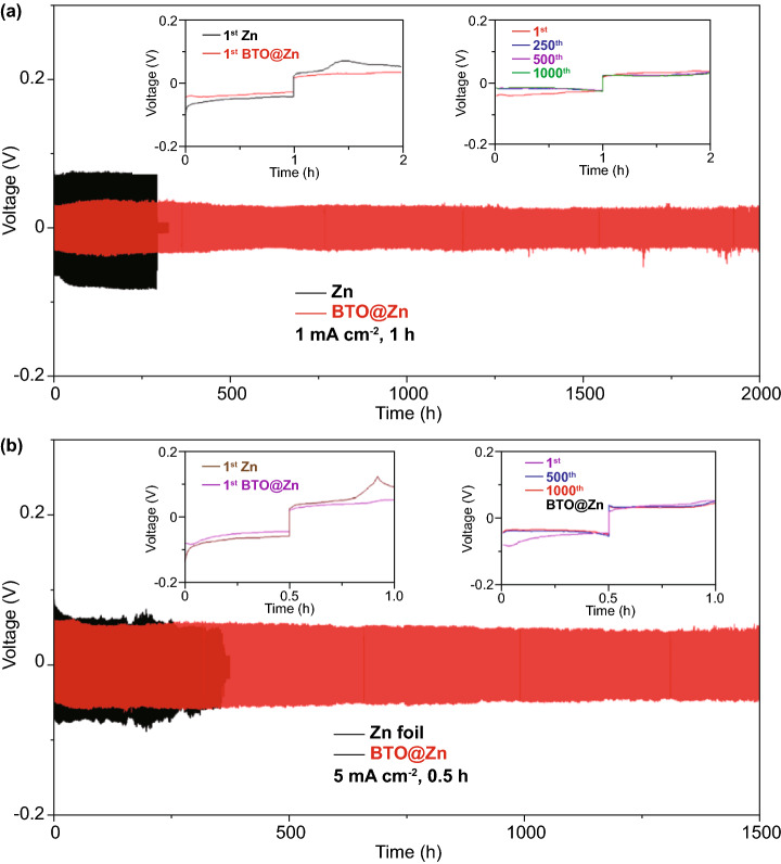
Aqueous zinc ion batteries show prospects for next-generation renewable energy storage devices. However, the practical applications have been limited by the issues derived from Zn anode. As one of serious problems, Zn dendrite growth caused from the uncontrollable Zn deposition is unfavorable. Herein, with the aim to regulate Zn deposition, an artificial solid–electrolyte interface is subtly engineered with a perovskite type material, BaTiO3, which can be polarized, and its polarization could be switched under the external electric field. Resulting from the aligned dipole in BaTiO3 layer, zinc ions could move in order during cycling process. Regulated Zn migration at the anode/electrolyte interface contributes to the even Zn stripping/plating and confined Zn dendrite growth. As a result, the reversible Zn plating/stripping processes for over 2000 h have been achieved at 1 mA cm−2 with capacity of 1 mAh cm−2. Furthermore, this anode endowing the electric dipoles shows enhanced cycling stability for aqueous Zn-MnO2 batteries. The battery can deliver nearly 100% Coulombic efficiency at 2 A g−1 after 300 cycles.
Supplementary Information: The online version of this article (10.1007/s40820-021-00599-2).
Keywords: Artificial solid–electrolyte interface; Perovskite type dielectric material; Regulated Zn deposition; Zn anode; Zn ion battery.
Figures


References
-
- Fang G, Zhou J, Pan A, Liang S. Recent advances in aqueous zinc-ion batteries. ACS Energy Lett. 2018;3:2480–2501. doi: 10.1021/acsenergylett.8b01426. - DOI
-
- Yi J, Liang P, Liu X, Wu K, Liu Y, et al. Challenges, mitigation strategies and perspectives in development of zinc-electrode materials and fabrication for rechargeable zinc–air batteries. Energy Environ. Sci. 2018;11:3075–3095. doi: 10.1039/c8ee01991f. - DOI
-
- Liang P, Yi J, Liu X, Wu K, Wang Z, et al. Highly reversible zn anode enabled by controllable formation of nucleation sites for Zn-based batteries. Adv. Funct. Mater. 2020;30:1908528. doi: 10.1002/adfm.201908528. - DOI
-
- Cao J, Zhang D, Zhang X, Sawangphruk M, Qin J, et al. A universal and facile approach to suppress dendrite formation for a Zn and Li metal anode. J. Mater. Chem. A. 2020;8:9331–9344. doi: 10.1039/d0ta02486d. - DOI
LinkOut - more resources
Full Text Sources
Research Materials