

Principles of Water Electrolysis and Recent Progress in Cobalt-, Nickel-, and Iron-Based Oxides for the Oxygen Evolution Reaction
- PMID: 34138511
- PMCID: PMC9291824
- DOI: 10.1002/anie.202103824
Principles of Water Electrolysis and Recent Progress in Cobalt-, Nickel-, and Iron-Based Oxides for the Oxygen Evolution Reaction
Abstract
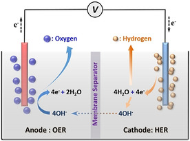
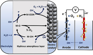
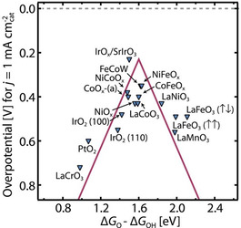
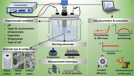
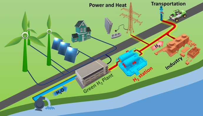
Water electrolysis that results in green hydrogen is the key process towards a circular economy. The supply of sustainable electricity and availability of oxygen evolution reaction (OER) electrocatalysts are the main bottlenecks of the process for large-scale production of green hydrogen. A broad range of OER electrocatalysts have been explored to decrease the overpotential and boost the kinetics of this sluggish half-reaction. Co-, Ni-, and Fe-based catalysts have been considered to be potential candidates to replace noble metals due to their tunable 3d electron configuration and spin state, versatility in terms of crystal and electronic structures, as well as abundance in nature. This Review provides some basic principles of water electrolysis, key aspects of OER, and significant criteria for the development of the catalysts. It provides also some insights on recent advances of Co-, Ni-, and Fe-based oxides and a brief perspective on green hydrogen production and the challenges of water electrolysis.
Keywords: cobalt; iron; nickel; oxygen evolution reaction; water splitting.
© 2021 The Authors. Angewandte Chemie International Edition published by Wiley-VCH GmbH.
Conflict of interest statement
The authors declare no conflict of interest.
Figures


Similar articles
-
Alkaline Water Electrolysis for Green Hydrogen Production.Acc Chem Res. 2024 Feb 9;57(4):558-67. doi: 10.1021/acs.accounts.3c00709. Online ahead of print. Acc Chem Res. 2024. PMID: 38335244 Free PMC article.
-
Hydrogen production by traditional and novel alkaline water electrolysis on nickel or iron based electrocatalysts.Chem Commun (Camb). 2023 Jun 29;59(53):8205-8221. doi: 10.1039/d3cc00996c. Chem Commun (Camb). 2023. PMID: 37293866 Review.
-
Waste-Derived Catalysts for Water Electrolysis: Circular Economy-Driven Sustainable Green Hydrogen Energy.Nanomicro Lett. 2022 Dec 1;15(1):4. doi: 10.1007/s40820-022-00974-7. Nanomicro Lett. 2022. PMID: 36454315 Free PMC article. Review.
-
Research on engineered electrocatalysts for efficient water splitting: a comprehensive review.Phys Chem Chem Phys. 2023 Mar 29;25(13):8992-9019. doi: 10.1039/d2cp05522h. Phys Chem Chem Phys. 2023. PMID: 36928479 Review.
-
Recent Progress in Cobalt-Based Heterogeneous Catalysts for Electrochemical Water Splitting.Adv Mater. 2016 Jan 13;28(2):215-30. doi: 10.1002/adma.201502696. Epub 2015 Nov 9. Adv Mater. 2016. PMID: 26551487
Cited by
-
Harnessing the electronic structure of active metals to lower the overpotential of the electrocatalytic oxygen evolution reaction.Chem Sci. 2023 Dec 12;15(4):1348-1363. doi: 10.1039/d3sc05891c. eCollection 2024 Jan 24. Chem Sci. 2023. PMID: 38274069 Free PMC article.
-
Unraveling the Role of the Stoichiometry of Atomic Layer Deposited Nickel Cobalt Oxides on the Oxygen Evolution Reaction.Adv Sci (Weinh). 2024 Aug;11(32):e2405188. doi: 10.1002/advs.202405188. Epub 2024 Jul 3. Adv Sci (Weinh). 2024. PMID: 38958233 Free PMC article.
-
Role of Fe decoration on the oxygen evolving state of Co3O4 nanocatalysts.Energy Environ Sci. 2024 Jan 30;17(5):2046-2058. doi: 10.1039/d3ee02809g. eCollection 2024 Mar 5. Energy Environ Sci. 2024. PMID: 38449571 Free PMC article.
-
Coupling Plant Polyphenol Coordination Assembly with Co(OH)2 to Enhance Electrocatalytic Performance towards Oxygen Evolution Reaction.Nanomaterials (Basel). 2022 Nov 11;12(22):3972. doi: 10.3390/nano12223972. Nanomaterials (Basel). 2022. PMID: 36432258 Free PMC article.
-
Alkaline Water Electrolysis for Green Hydrogen Production.Acc Chem Res. 2024 Feb 9;57(4):558-67. doi: 10.1021/acs.accounts.3c00709. Online ahead of print. Acc Chem Res. 2024. PMID: 38335244 Free PMC article.
References
-
- De Luna P., Hahn C., Higgins D., Jaffer S. A., Jaramillo T. F., Sargent E. H., Science 2019, 364, eaav3506. - PubMed
-
- A Hydrogen Strategy for A Climate Neutral Europe 2020, https://ec.europa.eu/energy/sites/ener/files/hydrogen strategy.pdf.
-
- van Renssen S., Nat. Clim. Change 2020, 10, 799–801.
-
- Grewe T., Deng X., Weidenthaler C., Schüth F., Tüysüz H., Chem. Mater. 2013, 25, 4926–4935.
Publication types
Grants and funding
LinkOut - more resources
Full Text Sources
Other Literature Sources
