

3D-Positioning of Nanoparticles in High-Curvature Block Copolymer Domains
- PMID: 34156739
- PMCID: PMC8362214
- DOI: 10.1002/anie.202102908
3D-Positioning of Nanoparticles in High-Curvature Block Copolymer Domains
Abstract
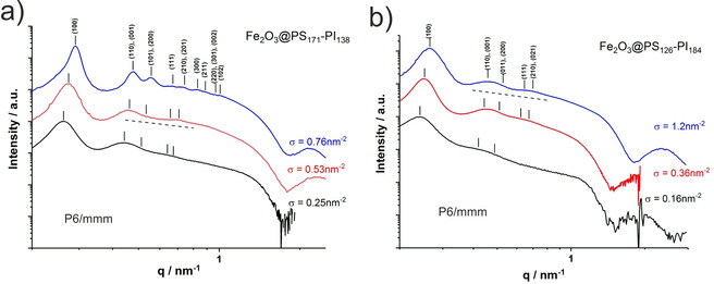
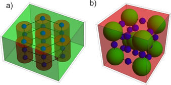
The defined assembly of nanoparticles in polymer matrices is an important precondition for next-generation functional materials. Here we demonstrate that a defined three-dimensional nanoparticle assembly within the unit cells can be realized by directly linking the nanoparticles to block copolymers. We show that for a range of nearly symmetric to unsymmetric block copolymers there are only two formed structures, a hexagonal lattice of P6/mmm-symmetry, where the nanoparticles are located in 1D-arrays within the cylindrical domains, and a cubic lattice of Im3m-symmetry, where the nanoparticles are located in the octahedral voids of a BCC-lattice, corresponding to the structure of ferrite steel. We observe the block length ratio and thus the interfacial curvature to be the most important parameter determining the lattice type. This is rationalized in terms of minimal chain extension such that domain topologies with large positive curvature are highly preferred. Already volume fractions of only one percent are sufficient to destabilize a lamellar structure and favor the formation of highly curved interfaces. The study thus demonstrates how nanoparticles can be located on well-defined positions in three-dimensional unit cells of block copolymer nanocomposites. This opens the way to functional 3D-nanocomposites where the nanoparticles need to be located on defined matrix positions.
Keywords: SAXS; TEM; block copolymers; nanocomposites; polymers.
© 2021 The Authors. Angewandte Chemie International Edition published by Wiley-VCH GmbH.
Conflict of interest statement
The authors declare no conflict of interest.
Figures


Similar articles
-
Controlled Assembly of Block Copolymer Coated Nanoparticles in 2D Arrays.Angew Chem Int Ed Engl. 2019 Jun 17;58(25):8541-8545. doi: 10.1002/anie.201901913. Epub 2019 May 13. Angew Chem Int Ed Engl. 2019. PMID: 31081290
-
Orientation of Nonspherical Nanoparticles in Ordered Block Copolymer for Functional Materials.ACS Appl Mater Interfaces. 2025 May 7;17(18):27238-27251. doi: 10.1021/acsami.5c04025. Epub 2025 Apr 22. ACS Appl Mater Interfaces. 2025. PMID: 40261826
-
Field-theoretic simulations of block copolymer nanocomposites in a constant interfacial tension ensemble.J Chem Phys. 2017 Apr 28;146(16):164903. doi: 10.1063/1.4981912. J Chem Phys. 2017. PMID: 28456215
-
Non-lamellar lipid liquid crystalline structures at interfaces.Adv Colloid Interface Sci. 2015 Aug;222:135-47. doi: 10.1016/j.cis.2014.11.003. Epub 2014 Nov 15. Adv Colloid Interface Sci. 2015. PMID: 25435157 Review.
-
Secondary Structure in Nonpeptidic Supramolecular Block Copolymers.Acc Chem Res. 2021 May 18;54(10):2397-2408. doi: 10.1021/acs.accounts.1c00028. Epub 2021 Apr 29. Acc Chem Res. 2021. PMID: 33914498 Review.
Cited by
-
Hybrid Time-Dependent Ginzburg-Landau Simulations of Block Copolymer Nanocomposites: Nanoparticle Anisotropy.Polymers (Basel). 2022 May 7;14(9):1910. doi: 10.3390/polym14091910. Polymers (Basel). 2022. PMID: 35567080 Free PMC article. Review.
References
-
- Boles M. A., Engel M., Talapin D. V., Chem. Rev. 2016, 116, 11220–11289. - PubMed
-
- Balasz A. C., Emrick T., Russell T. P., Science 2006, 314, 1107–1110. - PubMed
-
- Bockstaller M. R., Mickiewicz R. A., Thomas E. L., Adv. Mater. 2005, 17, 1331–1349. - PubMed
-
- Yoo M., Kim S., Bang J., J. Polym. Sci. Part B 2013, 51, 494–507.
-
- Kao J., Thorkelsson K., Bai P., Rancatore B. J., Xu T., Chem. Soc. Rev. 2013, 42, 2654–2678. - PubMed
Grants and funding
LinkOut - more resources
Full Text Sources
Research Materials
