. 2021 Jul 9;49(12):6996-7010.
doi: 10.1093/nar/gkab537.

Molecular characterization of both transesterification reactions of the group II intron circularization pathway

Affiliations

Molecular characterization of both transesterification reactions of the group II intron circularization pathway

Félix LaRoche-Johnston et al. Nucleic Acids Res. .

Abstract

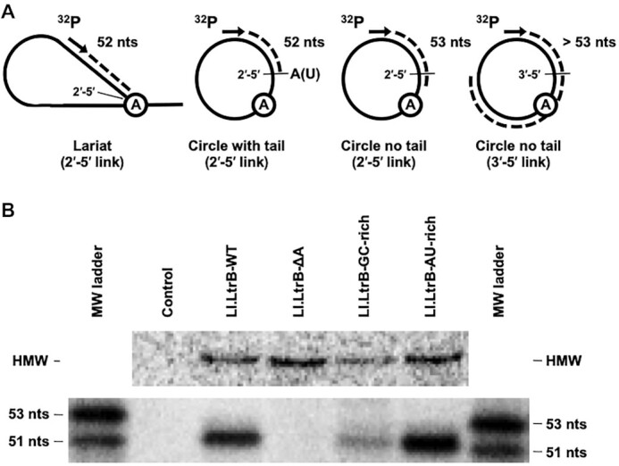
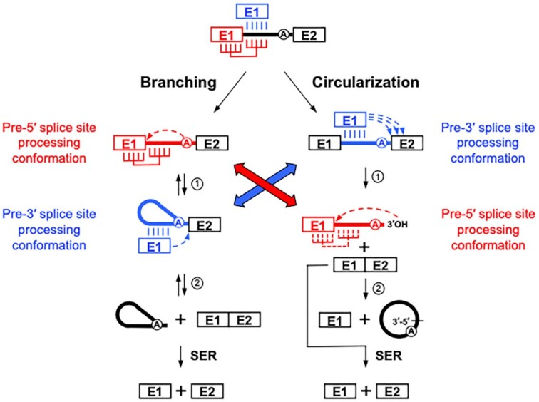
Group II introns can self-splice from RNA transcripts through branching, hydrolysis and circularization, being released as lariats, linear introns and circles, respectively. In contrast to branching, the circularization pathway is mostly based on assumptions and has been largely overlooked. Here, we address the molecular details of both transesterification reactions of the group II intron circularization pathway in vivo. We show that free E1 is recruited by the intron through base pairing interactions and that released intron circles can generate free E1 by the spliced exon reopening reaction. The first transesterification reaction was found to be induced inaccurately by the 3'OH of the terminal residue of free E1 at the 3' splice site, producing circularization intermediates with heterogeneous 3' ends. Nevertheless, specific terminal 3'OH, selected by a molecular ruler, was shown to precisely attack the 5' splice site and release intron circles with 3'-5' rather than 2'-5' bonds at their circularization junction. Our work supports a circularization model where the recruitment of free E1 and/or displacement of cis-E1 induce a conformational change of the intron active site from the pre-5' to the pre-3' splice site processing conformation, suggesting how circularization might initiate at the 3' instead of the 5' splice site.


Figures

Figure 1.
Figure 1.
Group II intron secondary structure and splicing pathways. Schematics depicting the secondary structure of group II introns and the currently accepted branching, circularization and hydrolysis splicing pathways are displayed. (A) The consensus secondary structure of group II introns consists of six domains (DI–DVI) radiating from a central wheel. The flanking exons (E1 and E2) are shown as boxes on either side of the intron, while the bulged A nucleotide in DVI is represented as a circled A. The base pairing interactions between the intron (exon binding sites 1 and 2, EBS1 and EBS2) and the last nucleotides of E1 (intron binding sites 1 and 2, IBS1 and IBS2) involved in the recognition of the 5′ splice site during splicing and reverse splicing are also depicted (EBS1–IBS1, yellow; EBS2–IBS2, green). Most group II introns harbour an open reading frame also called IEP in DIV. (B) Branching: The 2′OH residue of the branch point A nucleotide (circled A) initiates the first nucleophilic attack at the 5′ splice site (step 1, dashed arrow). This transesterification reaction connects the 5′ end of the intron to the branch point A residue creating a 2′–5′ link and releases E1 that remains associated with the intron through base pairing interactions (EBS1/2–IBS1/2, vertical lines). The liberated 3′OH at the 3′ end of E1 then initiates a second nucleophilic attack at the 3′ splice site (step 2, dashed arrow), ligating the two exons (E1–E2) and releasing the intron as a branched lariat. (C) Circularization: The first nucleophilic attack takes place at the 3′ splice site and is initiated by the 3′OH of the last residue of free E1 (step 1, dashed arrow). This transesterification reaction generates ligated exons (E1–E2) and a circularization intermediate where the 5′ end of the linear intron is still attached to E1. Next, the 2′OH of the last intron residue initiates the second nucleophilic reaction at the 5′ splice site (step 2, dashed arrow) resulting in the release of intron circles and free E1. The position of the circularization junction (CJ) of released intron circles is depicted by a black bar. (D) Hydrolysis: A hydroxyl residue or water molecule initiates the first reaction at the 5′ splice site (step 1, dashed arrow). The second nucleophilic attack at the 3′ splice site is initiated by the liberated 3′OH of the last residue of E1 (step 2, dashed arrow), which ligates the two exons (E1–E2) and releases a linear intron. The circularization pathway is unique in that it requires free E1 while the first transesterification reaction is initiated in trans and occurs at the 3′ instead of the 5′ splice site. Even though the second circularization step generates free E1 (C, step 2) that can be recruited by the intron in a pre-mRNA to initiate another round of circularization (a), it is unclear how free E1 is initially produced. Other potential sources of free E1 are the spliced exon reopening (SER) reaction catalysed by released lariats (B, SER, b) and linear introns (D, SER, c).
Figure 2.
Figure 2.
Free E1 initiates in trans the first transesterification reaction of the group II intron circularization pathway in vivo. Two versions of the ltrB gene, interrupted by identical copies of the Ll.LtrB branch point mutant (Ll.LtrB-ΔA), were expressed constitutively (P23 promoter) in L. lactis [NZ9800(recA+) or MMS372(recA−)] from two independent plasmids, pDL (red) and pLE (blue). The absence of the branch point A residue and the released intron circularization junction are illustrated by an empty circle and CJ, respectively. Splicing of Ll.LtrB-ΔA from both pre-mRNAs is represented by two schematics of the group II intron circularization pathway (red and blue). E1 was mutated from GTC to CAG (asterisks) upstream of the intron binding sequences (IBS1/2) at positions −24 to −22 in pDL-P232-E1(CAG)-Ll.LtrB-ΔA-E2(AAT) (red pathway), while E2 was mutated from AAT to TTA (asterisks) at positions +22 to +24 in pLE-P232-E1(GTC)-Ll.LtrB-ΔA-E2(TTA) (blue pathway). The use of cognate free E1 by each intron is represented by solid arrows, while the use of the counterpart free E1 by both introns is represented by dashed arrows. The pool of ligated exons (E1−E2) from NZ9800(recA+) and MMS372(recA−) was independently amplified by RT-PCR, cloned in pBS and 100 independent clones were sequenced. The relative abundance of the four combinations of ligated exons is shown as percentages.
Figure 3.
Figure 3.
External sources of free E1 can be recruited to initiate the group II intron circularization pathway. (A) Schematic of the ex vivo group II intron circularization assay. The assay consists of adding various amounts [No oligo Ctl, E1(1×), E1(2×) or E1(4×)] of a short DNA oligo (DNA E1, red) as an external source of free E1 to L. lactis cell lysates expressing various constructs of the Ll.LtrB intron to assess whether the intron can recruit free E1 to initiate circularization and generate ligated exons. The internal source of E1 coming from the pre-mRNA contains the wild-type GTC sequence at positions −24 to −22 [RNA E1: E1(GTC)], upstream of the intron binding sequences (IBS1/2), whereas the external source of E1 (red) contains CAG (asterisks) [DNA E1: E1(CAG)]. The schematic of the assay shows that the intron can use in trans either the internal or external source of E1 (dashed curved arrows) to produce two types of ligated exons: E1(GTC)–E2 or E1(CAG)–E2. A portion of the sequence chromatogram of the purified PCR amplicons spanning nucleotides −26 to −20 from the end of E1 is shown where nucleotides −24 to −22 are boxed. Nucleotides GTC or CAG are present at positions −24 to −22, depending on whether the internal or external source of E1 is found ligated to E2, respectively. A mixed sequence at positions −24 to −22 is thus expected in the chromatogram if both sources of ligated exons are generated. The colour code above each base is a visual representation of the Phred score calculated for base calling from 0 to 60 (red to blue). Ligated exons were amplified by RT-PCR from total RNA extracts containing Ll.LtrB-WT (Ll.LtrB-WT) (B, CE) and Ll.LtrB-WT-ΔSDΔAUG (Ll.LtrB-ΔΔ) (D). Some bacterial cultures were treated with rifampicin (C) or erythromycin (E) before cell lysis to block transcription and translation, respectively.
Figure 4.
Figure 4.
Free E1 is recruited by base pairing interactions to initiate the group II intron circularization pathway. (A) Schematic of the ex vivo group II intron circularization assay. The assay consists of adding short DNA oligos (DNA E1, red) as external sources of free E1 to L. lactis cell lysates expressing various constructs of the Ll.LtrB intron to assess how the intron recruits free E1 to initiate circularization and generate ligated exons. Ll.LtrB-WT (top left) and a variant with swapped IBS1/EBS1 sequences between E1 and the intron [Ll.LtrB-IBS1-EBS1 swap (Ll.LtrB-SW)] (bottom left) were used. The EBS1–IBS1 (yellow) and EBS2–IBS2 (green) base pairing interactions between the intron and E1 are represented by black [cognate trans E1 (E1(GTC))] and red [external trans E1 (E1(CAG))] arrows. The internal source of E1 coming from the pre-mRNA contains the wild-type GTC sequence at positions −24 to −22 [RNA E1: E1(GTC)], upstream of the intron binding sequences (IBS1/2), whereas the external source of E1 (red) contains CAG (asterisks) [DNA E1: E1(CAG)]. The schematic of the assay shows that the intron can use in trans either the internal or external source of E1 (dashed curved arrows) to produce two types of ligated exons: E1(GTC)–E2 or E1(CAG)–E2. A portion of the sequence chromatogram of the purified PCR amplicons spanning nucleotides −26 to −20 from the end of E1 is shown where nucleotides −24 to −22 are boxed. Nucleotides GTC or CAG are present at positions −24 to −22, depending on whether the internal or external source of E1 is found ligated to E2, respectively. A mixed sequence at positions −24 to −22 is thus expected in the chromatogram if both sources of ligated exons are generated. The colour code above each base is a visual representation of the Phred score calculated for base calling from 0 to 60 (red to blue). Ligated exons were amplified by RT-PCR from total RNA extracts containing Ll.LtrB-WT (Ll.LtrB-WT) (B, C, D), Ll.LtrB-ΔA (B, C, D) and Ll.LtrB-IBS1-EBS1 swap (Ll.LtrB-SW) (B). While the E1(CAG) DNA oligos (E1-WT and E1-SW) were 54 nt in length (B, C), the E1(CAG)-CACCCCCCCC oligos used for the SER assay (SER-WT and SER-SW) were 64 nt long (D, SER). The nucleotides at positions 3–10 of E2 were replaced by a stretch of C residues to distinguish the ligated exons provided in trans from the cognate ligated exons.
Figure 5.
Figure 5.
The first and last residues of released intron circles are joined by a 3′–5′ phosphodiester bond. Primer extension assays were performed across the Ll.LtrB branching and circularization junctions using the AMV RT. (A) Schematic of the various potential pause sites of the AMV RT at the branching and circularization junctions of different released intron lariats and circles. Extension (dashed line) of the 32P-labelled primer (arrow) across the branching and circularization junctions may lead to bands of 52 nt [lariat (formed following branching), 2′–5′ link with a 3′ tail; circle with tail (formed following circularization where the attacking nucleophile is a 2′OH upstream of terminal nucleotide), 2′–5′ link with a 3′ tail], 53 nt [circle with no tail (formed following circularization where the attacking nucleophile is the 2′OH of terminal intron nucleotide), 2′–5′ link without a 3′ tail] or no bands (circle with no tail, 3′–5′ link). (B) Denaturing 12% polyacrylamide gel of primer extensions across the branching and circularization junctions of different Ll.LtrB variants. The two bands used as molecular weight markers (MW ladder) were generated using poisoned primer extension by adding high concentrations of dideoxy CTP during cDNA synthesis (23,33) and correspond to unspliced precursor mRNA (53 nt) and ligated exons (51 nt) of Ll.LtrB-WT expressed from pDL-P232-Ll.LtrB-WT. The top of the gel reveals the presence of much higher molecular weight bands (HMW).
Figure 6.
Figure 6.
The 3′OH that initiates the second nucleophilic attack of the group II intron circularization pathway is selected by a molecular ruler. (A) The 3′ ends of circularization intermediates were identified by 3′ RACE. Free intron 3′ ends were amplified by RT-PCR from L. lactis total RNA extracts. Intron 3′ ends were identified by first extending the intron RNA with a poly(A) tail followed by the synthesis of cDNA with an oligo dT. The RNA strand was removed by an RNAse H treatment and the single-strand DNA amplified by PCR. The same procedure was repeated for all constructs but extending a poly(U) instead of a poly(A) tail at the 3′ end of the intron (Supplementary Figure S2). (B) The nucleotides present at the circularization junction of released intron circles were identified by RT-PCR. The primers used are represented by grey (RT) and black (PCR) arrows. The absence of the branch point A residue is illustrated by an empty circle. (C) The 3′ splice site of five Ll.LtrB-ΔA constructs is depicted showing the last stem of DVI attached to E2 (boxed sequence). One or two nucleotides were removed [Ll.LtrB-ΔA(−A), Ll.LtrB-ΔA(−AC)] or added [Ll.LtrB-ΔA(+A), Ll.LtrB-ΔA(+AA)] to the linker between DVI and E2 of Ll.LtrB-ΔA. Vertical lines represent free 3′ ends identified by 3′ RACE (A), while the nucleotides found at circularization junctions (B) are shown as percentages. The most represented sequences at the circularization junction mostly correspond for all the intron variants studied to the third nucleotide from the bottom of the DVI stem (red nucleotide). (D) Molecular details of both steps of the group II intron circularization pathway for the Ll.LtrB-ΔA construct. Prior to the initiation of the first step of the circularization pathway, the unspliced intron recruits free E1 through specific base paring interactions between the intron EBS1/2 and the E1 IBS1/2 sequences (vertical lines). The first step of the pathway is initiated at the 3′ splice site of the pre-mRNA by the 3′OH of the recruited free E1 (step 1). The first transesterification reaction is not always accurate (step 1, dashed arrows) and generates circularization intermediates with different 3′ ends along with their corresponding ligated exons. Circularization intermediates with 5 and 6 nt from the base of the DVI stem (DVI + 5 nt, DVI + 6 nt) were identified by 3′ RACE (C, vertical lines). Next, the favoured nucleophile to initiate the second transesterification reaction is the 3′OH of the third nucleotide after the base of the DVI stem (DVI + 3 nt) (step 2, dashed arrow). The great majority of the Ll.LtrB-ΔA released circles (95%) have an extra C at the circularization junction and were generated by the circularization intermediate with 3 nt after DVI. The 3′OH of the third nucleotide seems to be at the optimal distance to be positioned within the intron active site. A small number of Ll.LtrB-ΔA released circles were generated from circularization intermediates with 2 nt (3%) and 4 nt (2%) after DVI. The 3′OH of the detected intermediates with 5 nt (CAU) and 6 nt (CAUA) after DVI is not used by the intron to initiate the second step of the pathway.
Figure 7.
Figure 7.
Model of the active site conformations between both steps of the circularization and branching splicing pathways. During the intron folding pathway, the IBS1/2 sequences of cis-E1, covalently attached to the intron 5′ end, bind to the EBS1/2 of the intron through base pairing interactions (top, red vertical lines). Following complete intron folding, free E1 competes with cis-E1 to base pair with the EBS1/2 motifs of the intron (top, blue vertical lines). Branching: The intron adopts the pre-5′ splice site processing conformation (red) when cis-E1 is base paired to the intron (red vertical lines). This leads to the nucleophilic attack of the 5′ splice site by the 2′OH of the branch point nucleotide (step 1, red dashed arrow). Cleavage of the 5′ splice site during the first step of branching was proposed to trigger a significant rearrangement of the catalytic site putting the intron in the pre-3′ splice site processing conformation (blue) and allowing for the second reaction to occur at the 3′ splice site (step 2, blue dashed arrow). Circularization: The displacement of cis-E1 in conjunction with the binding of free E1 to the intron EBS1/2 motifs (blue vertical lines) causes a significant rearrangement of the catalytic site, putting the intron in the pre-3′ splice site processing conformation (blue). This allows for the first circularization reaction to occur at the 3′ splice site (step 1). Recognition of the intron–E2 3′ splice site is imprecise (blue dashed arrows) producing a series of E1–intron splicing intermediates with different 3′ ends. The first step of circularization is equivalent to the second step of branching (blue double-headed arrow): E1 is base paired to the intron but not covalently attached to its 5′ end, while the 3′OH of E1 attacks the 3′ splice site leading to the release of ligated exons. Cleavage of the 3′ splice site and the release of ligated exons during the first step of circularization trigger a significant rearrangement of the catalytic site putting the intron in the pre-5′ splice site processing conformation (red) and allowing for the second reaction to occur at the 5′ splice site (step 2). The nucleophile is chosen using a molecular ruler and the recognition of the E1–intron 5′ splice site is accurate (red dashed arrow). The second step of circularization is equivalent to the first step of branching (red double-headed arrow): the attack at the 5′ splice site closes the intron structure in lariat or circle form and releases free E1. However, in the second step of circularization, E1 is most likely not base paired to the intron (dashed red vertical lines) since it is not the 2′OH of the branch point nucleotide but rather the 3′OH of the last nucleotide of the intron, 6 nt further away, that induces the nucleophilic attack. Our work also demonstrated that released intron circles harbour a 3′–5′ link at their circularization junctions and can contribute to the generation of free E1 by processing ligated exons (E1–E2) through the SER reaction similarly to released intron lariats.

Similar articles

Cited by

References

    1. Lambowitz A.M., Zimmerly S.. Group II introns: mobile ribozymes that invade DNA. Cold Spring Harb. Perspect. Biol. 2011; 3:a003616. - PMC - PubMed
    1. Chalamcharla V.R., Curcio M.J., Belfort M.. Nuclear expression of a group II intron is consistent with spliceosomal intron ancestry. Genes Dev. 2010; 24:827–836. - PMC - PubMed
    1. Lambowitz A.M., Belfort M.. Mobile bacterial group II introns at the crux of eukaryotic evolution. Microbiol. Spectr. 2015; 3:MDNA3-0050-2014. - PMC - PubMed
    1. McNeil B.A., Semper C., Zimmerly S.. Group II introns: versatile ribozymes and retroelements. Wiley Interdiscip. Rev. RNA. 2016; 7:341–355. - PubMed
    1. Michel F., Ferat J.L.. Structure and activities of group II introns. Annu. Rev. Biochem. 1995; 64:435–461. - PubMed

Publication types