. 2021 Jun 23;11(1):13127.
doi: 10.1038/s41598-021-92247-3.

Electro-steric opening of the CLC-2 chloride channel gate

Affiliations

Electro-steric opening of the CLC-2 chloride channel gate

José J De Jesús-Pérez et al. Sci Rep. .

Abstract

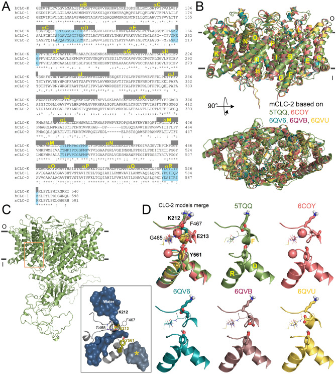
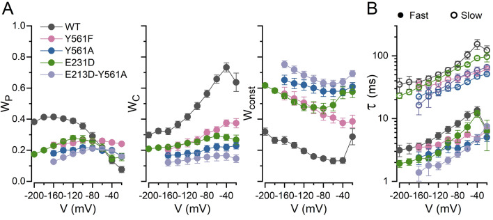
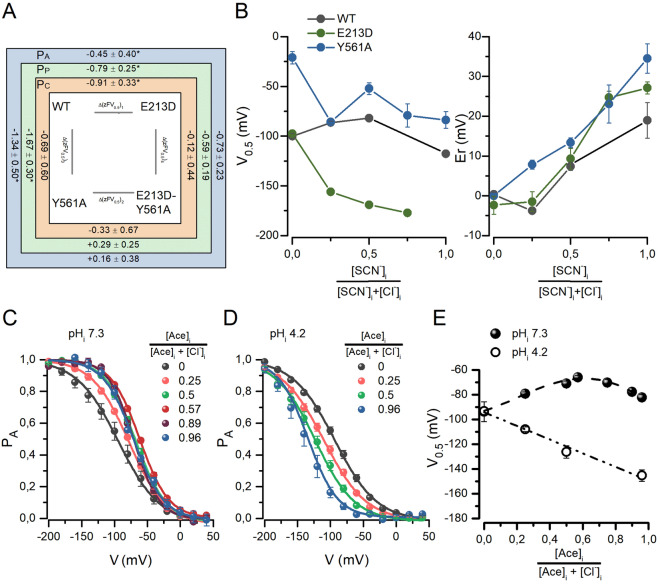
The widely expressed two-pore homodimeric inward rectifier CLC-2 chloride channel regulates transepithelial chloride transport, extracellular chloride homeostasis, and neuronal excitability. Each pore is independently gated at hyperpolarized voltages by a conserved pore glutamate. Presumably, exiting chloride ions push glutamate outwardly while external protonation stabilizes it. To understand the mechanism of mouse CLC-2 opening we used homology modelling-guided structure-function analysis. Structural modelling suggests that glutamate E213 interacts with tyrosine Y561 to close a pore. Accordingly, Y561A and E213D mutants are activated at less hyperpolarized voltages, re-opened at depolarized voltages, and fast and common gating components are reduced. The double mutant cycle analysis showed that E213 and Y561 are energetically coupled to alter CLC-2 gating. In agreement, the anomalous mole fraction behaviour of the voltage dependence, measured by the voltage to induce half-open probability, was strongly altered in these mutants. Finally, cytosolic acidification or high extracellular chloride concentration, conditions that have little or no effect on WT CLC-2, induced reopening of Y561 mutants at positive voltages presumably by the inward opening of E213. We concluded that the CLC-2 gate is formed by Y561-E213 and that outward permeant anions open the gate by electrostatic and steric interactions.


Conflict of interest statement

The authors declare no competing interests.

Figures

Figure 1
Figure 1
Homology models of the CLC-2 structure. (A) Sequence alignment of the transmembrane region of bovine CLC-K (bCLC-K), human CLC-1 (hCLC-1), and mouse CLC-2 (mCLC-2). Residues forming B-R alpha helices are shown in grey and pore region residues are highlighted in blue. (B) Structural alignment of the homology models for the CLC-2 structure. Homology structures were built using the cryo-EM structure of CLC-K (5TQQ, green) and hCLC-1 (6COY, salmon; 6QV6, cyan; 6QVB, redwood; 6QVU, yellow) channels as templates. Views of the transmembrane domains (yellow letters) perpendicular to membrane plane (above) and from the top (below). Parallel grey lines indicate external (o) and internal (i) membrane limits. The RMSD of backbone atoms were < 0.31 Å and the C-score = 1.98 calculated by I-Tasser (2 is the upper limit). (C) mCLC-2CLC-K model structure showing the transmembrane and intracellular cystathionine-β-synthase (CBS) domains. The external and internal membrane limits are indicated by parallel grey lines. The orange square indicates the intracellular pore region shown in (D). Grey square shows the canonical pore flooded with water represented as a dark surface. The intracellular alternative pathway, unconnected to the canonical pore, is shown in grey marked with a yellow asterisk. Y561 and E213 are in olive. (D) Pore region of mCLC-2 models. Pore regions superposition (CLC-2 models merge) from homology structures. Sticks represent K212, E213, and Y561. The sidechain of E213 adopted different positions depending on the template; away from Y561 in 5TQQ, 6COY, and 6QV6 based models and closer to Y561 in 6QVB and 6QVU based models. Chloride ions (pink spheres) from hCLC-1 6COY were placed in the 6COY-based CLC-2 model.
Figure 2
Figure 2
Voltage-dependent activation of CLC-2 depends on both Y561 and E213. (A) Colour coded Cl currents recorded from five different HEK293 cells expressing WT CLC-2, Y561F, Y561A, E213D, and E213D-Y561A channels. Cl currents were elicited by the voltage protocol shown in the upper left corner. The protocol consisted of voltage steps from − 160 or − 200 to + 200 mV in 20 mV increments and a repolarization voltage to + 80 mV to record tail currents. We intercalated a 15 ms/− 200 mV step and used the magnitude of the currents measured before and after the interpulse (red and blue arrows, respectively) to calculate the open probability of pore (PP) and common (PC) gates (see methods). Cl currents were recorded using pHi = pHo = 7.3 and [Cl]i = [Cl]o = 140 mM. (B) The voltage dependency of the apparent open probability (PA, spheres), pore (PP, circles) and common (PC, squares) gates computed for WT CLC-2, Y561F, Y561A, E213D, and E213D-Y561A channels. Upper row: PA; lower row: PP and PC. Continuous lines are fits with a single (PA of WT, Y561F, and E213D; PP of WT and Y561F; PC of all channels) or double (PA of Y561A and E213D-Y561A; PP of Y561A, E213D, and E213D-Y561A) Boltzmann equation to determine voltage-dependent parameters V0.5 and z listed in Table 1.
Figure 3
Figure 3
Kinetics analysis of WT and Y561 and E213 mutant channels. (A) The relative contribution of fast (WP), slow (WC) and constant (Wconst) components of the total Cl current generated by the colour coded indicated channels. (B) Voltage dependence of fast (τf, closed circles) and slow (τs, open circles) time constants of the Cl currents generated by the channels indicated in (A). Whole cell Cl currents were fitted with a biexponential function (Eq. 2) to determine Wp, WC, Wconst, τf, and τs.
Figure 4
Figure 4
Double mutant cycle analysis and anomalous mole fraction behaviour show coupling of E213 and Y561. (A) Double mutant cycle analysis. The analysis was performed using the z and V0.5 obtained for PA (blue square), PP (green square), and PC (orange square) for the WT, E213D, Y56A and E213D-Y561A channels listed in Table 1. Δ(zFV0.5)1, Δ(zFV0.5)2, Δ(zFV0.5)3, and Δ(zFV0.5)4 are the energy change in the voltage-dependent gating caused by a given mutation calculated using Eq. (1). For example, Δ(zFV0.5)1 is the energy change induced by mutating E213 in the WT CLC-2. The listed energy change values are in kCal/mol. The asterisks indicate statistically significant different pair Δ(zFV0.5)1:Δ(zFV0.5)2 and Δ(zFV0.5)3:Δ(zFV0.5)4 values. (B) Anomalous mole fraction behaviour of the voltage-dependent activation and reversal potential of WT (n = 5–9), E213D (n = 6–10), and Y561A (n = 4–7) channels. AMF behaviour was evaluated using SCN/Cl mixtures. V0.5 values were calculated using the Boltzmann equation to fit the negative portion of the curves whereas Er was calculated by interpolation in the current–voltage relationships. At SCN mole fraction = 1, we could not determine E213D V0.5. (C,D) Voltage-dependent activation determined at pHi of 7.3 (n = 5–10) and 4.2 (n = 5–7) using different acetate mole fractions. PA was calculated using the tail current magnitude. The resulting curves were normalized to their respective tail current maximum obtained after fitting curves with the Boltzmann equation. Continuous lines are fits from which the voltage-dependent parameters V0.5 and z were computed. (E) V0.5 plotted against acetate mole fractions. Filled symbols correspond to data obtained at pHi 7.3 whereas open symbols were collected at pHi 4.2. V0.5 values were obtained from Boltzmann fits to data shown in panels C and D.
Figure 5
Figure 5
Y561F and Y561A CLC-2 mutant channels are sensitive to extracellular chloride. (A–C) Top panels: Cl currents recorded from HEK293 cells expressing WT CLC-2 (A), Y561F (B), or Y561A (C) exposed first to 140 (grey) and then 10 (blue) mM [Cl]o. [Cl]i = 140 mM and pHi = pHo = 7.3. Channels were activated using the voltage protocol shown in Fig. 2A. (A–C) Bottom panels: Voltage dependence of PA (left), PP (middle), and PC (right) for WT CLC-2 (A), Y561F (B) and Y561A (C) determined first with 140 (grey) and then with 10 (blue) mM [Cl]o. [Cl]i = 140 mM and pHi = pHo = 7.3. Lines are fits of the data with a single (A,B, and PA from 10 mM Cl data and PC in C) or double (PA from 140 mM Cl data and PP in C) Boltzmann equation. Voltage-dependent parameters V0.5 and z are listed in Table 1.
Figure 6
Figure 6
Y561F and Y561A CLC-2 mutant channels are sensitive to intracellular protons. (A) Intracellular acidification did not alter the voltage dependence of WT CLC-2 PA. Recordings like those shown on the left side were analysed to construct PA vs V relations at pHi of 7.3 (grey) and 4.2 (red). The voltage-dependent parameters V0.5 were -93.9 ± 7.9 mV and -93.4 ± 3.4 mV, at pHi 7.3 and 4.2, respectively (n = 5). (B,C) Top panels. Cl currents from three different HEK293 cells expressing the Y561F (B) or Y561A (C) mutants were recorded in the presence of 140 mM intracellular Cl and intracellular pH 7.3 (grey), 5.5 (blue), 4.3 (red). The voltage protocol showed in Fig. 2A was utilized in these experiments. Extracellular pH and [Cl]o were 7.3 and 140 mM, respectively. (B,C) Bottom panels. Voltage dependence of PA, PP and PC for Y561F (B) and Y561A (C) are plotted using data collected at pHi 7.3 (grey), 5.5 (blue) and 4.3 (red). Lines in (A–C) plots are fits of the data with a single (PA in A; PA and PP at pHi 7.3 and 5.5 and PC in B; PC in C) or double (PA and PP at pHi 4.3 in B; PA and PP in C) Boltzmann equation used to calculate V0.5 and z parameters listed in Table 1.
Figure 7
Figure 7
Schematic representation of the electro-steric activation of CLC-2. The Scheme depicts one pore and the side chains of E174, K568, Y561, E213 and K212 lining the pore. The empty pore remains closed by the Y561-E213 gate (A). Upon a hyperpolarization (V < 0), intracellular Cl occupies the pore initiating the activation process (B). The gate is splited by electro-steric repulsion and E213 adopts an outward-facing conformation thus coupling permeation to gating (C).

References

    1. Hille, B., Armstrong, C. M. & MacKinnon, R. Ion channels: From idea to reality. Nat. Med.5, 1105–1109. 10.1038/13415 (1999). - PubMed
    1. Bezanilla F. How membrane proteins sense voltage. Nat. Rev. Mol. Cell Biol. 2008;9:323–332. doi: 10.1038/nrm2376. - DOI - PubMed
    1. Long, S. B., Campbell, E. B. & MacKinnon, R. Voltage sensor of Kv1.2: Structural basis of electromechanical coupling. Science309, 903–908. 10.1126/science.1116270 (2005). - PubMed
    1. Jiang, Y., Ruta, V., Chen, J., Lee, A. & Mackinnon, R. The principle of gating charge movement in a voltage-dependent K+ channel. 423, 42–48 (2003). - PubMed
    1. Bezanilla F. Voltage sensor movements. J. Gen. Physiol. 2002 doi: 10.1085/jgp.20028660. - DOI - PMC - PubMed

Publication types