. 2018 Apr;3(4):18016.
doi: 10.1038/natrevmats.2018.16. Epub 2018 Apr 5.

Nanofibrils in nature and materials engineering

Affiliations

Nanofibrils in nature and materials engineering

Shengjie Ling et al. Nat Rev Mater. 2018 Apr.

Abstract

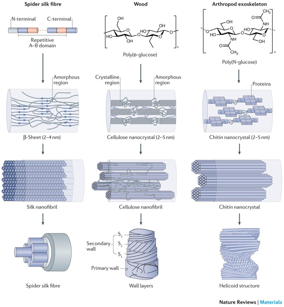
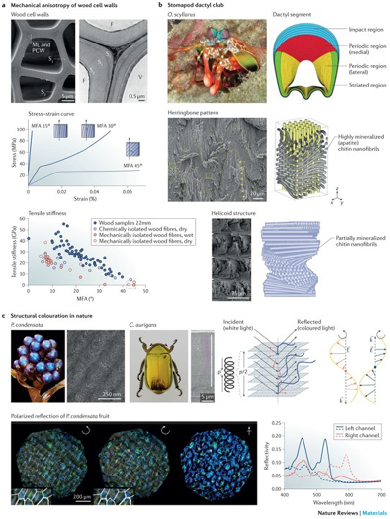
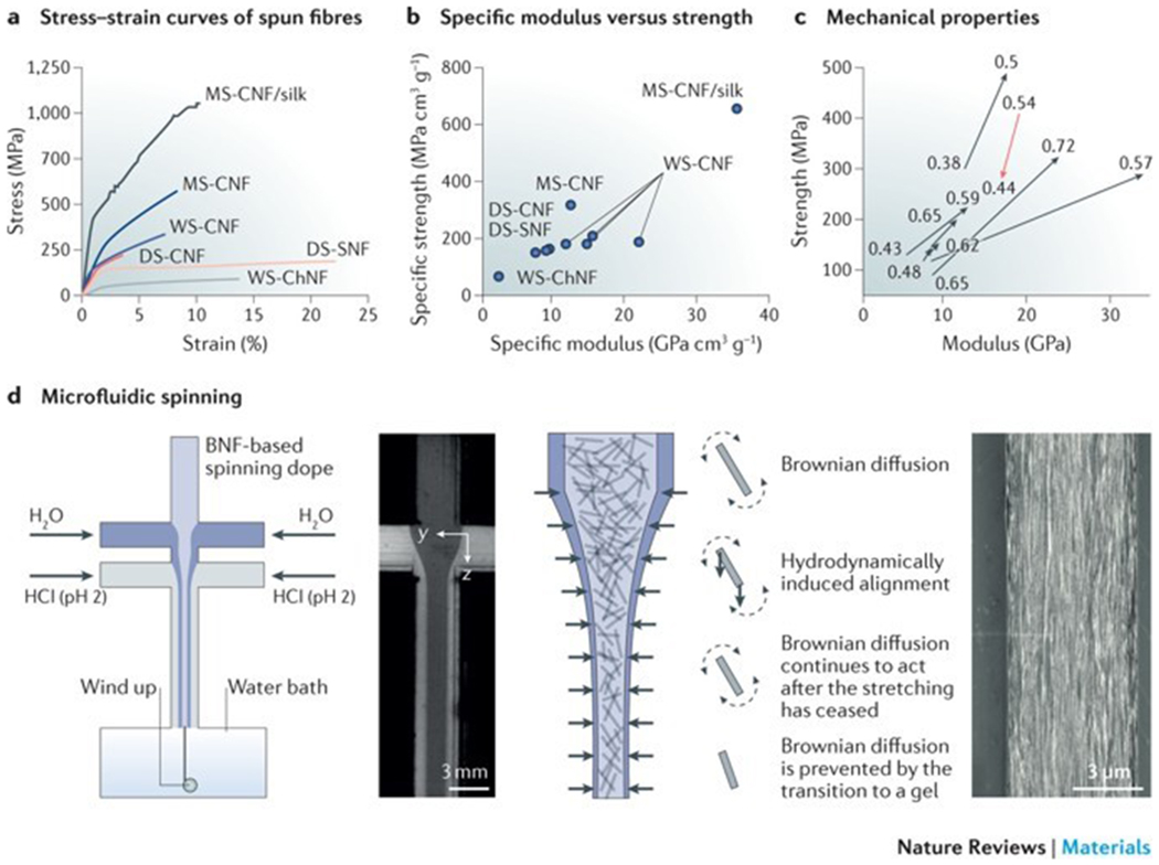
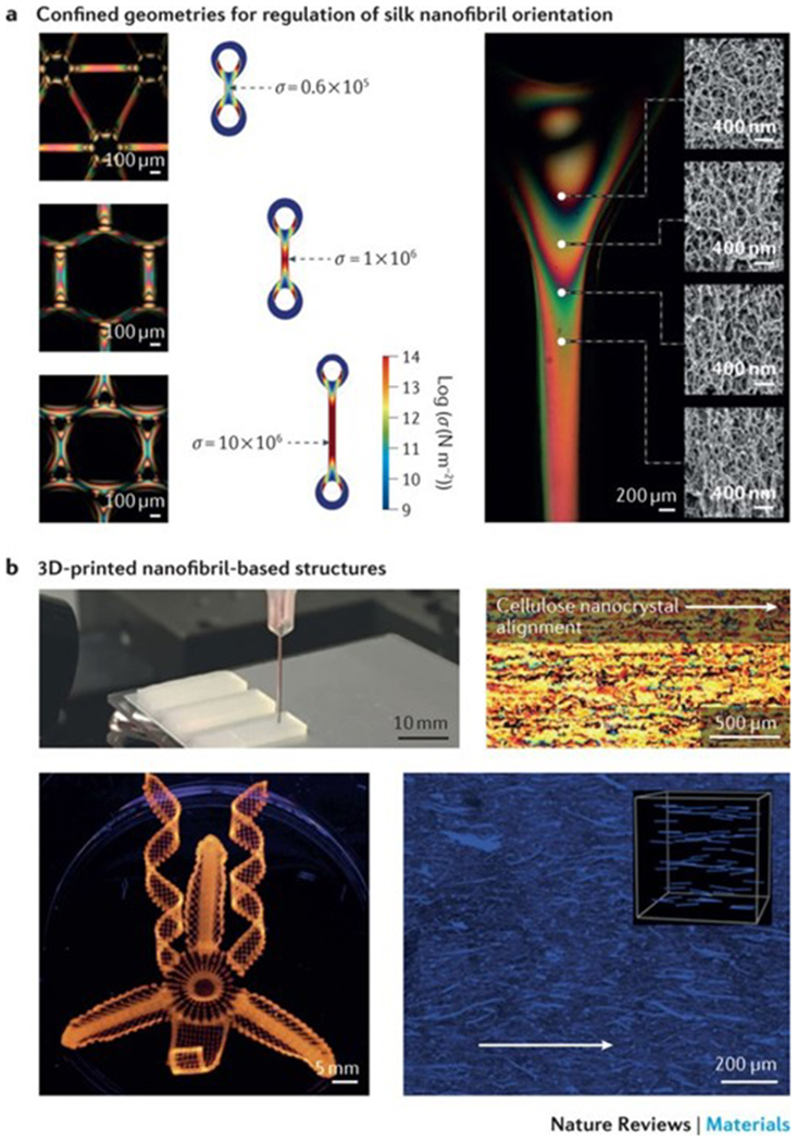
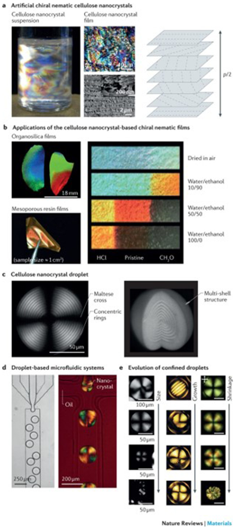
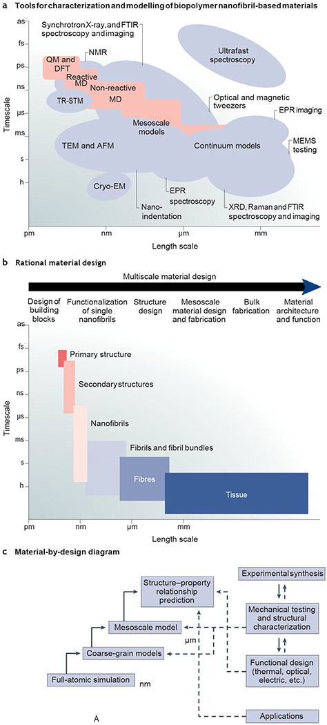
Nanofibrillar materials, such as cellulose, chitin and silk, are highly ordered architectures, formed through the self-assembly of repetitive building blocks into higher-order structures, which are stabilized by non-covalent interactions. This hierarchical building principle endows many biological materials with remarkable mechanical strength, anisotropy, flexibility and optical properties, such as structural colour. These features make nanofibrillar biopolymers interesting candidates for the development of strong, sustainable and biocompatible materials for environmental, energy, optical and biomedical applications. However, recreating their architecture is challenging from an engineering perspective. Rational design approaches, applying a combination of theoretical and experimental protocols, have enabled the design of biopolymer-based materials through mimicking nature's multiscale assembly approach. In this Review, we summarize hierarchical design strategies of cellulose, silk and chitin, focusing on nanoconfinement, fibrillar orientation and alignment in 2D and 3D structures. These multiscale architectures are discussed in the context of mechanical and optical properties, and different fabrication strategies for the manufacturing of biopolymer nanofibril-based materials are investigated. We highlight the contribution of rational material design strategies to the development of mechanically anisotropic and responsive materials and examine the future of the material-by-design paradigm.


Conflict of interest statement

Competing interests The authors declare no competing interests.

Figures

Figure 1|
Figure 1|. Hierarchical structure of silk, cellulose and chitin.
Silk, wood and exoskeletons of arthropods are formed following the same multiscale construction principle. The smallest units of silk fibrils are highly repetitive core sequences of amino acids with hydrophilic and hydrophobic segments (repetitive A–B domain), which are flanked by terminal domains (N-terminal and C-terminal). The hydrophilic domains assemble into random coils and/or helical structures, and the hydrophobic domains transition into β-sheet structures. Cellulose consists of a linear chain of β-(1,4)-linked d-glucose units,, and chitin is made of a long-chain polymer of (1,4)-β-N-acetylglucosamine. The nanocrystal size of the respective crystalline units is confined to several nanometres. The nanocrystals assemble into fibrils with an orientation along the longitudinal axis, which can be further organized into 2D laminar and 3D helicoidal architectures at the micrometre scale in silk fibres, cell wall layers and exoskeletons. S, secondary wall layer. The wall layers are reproduced from REF. , Macmillan Publishers Limited. The helicoid structure is adapted with permission from REF. , Elsevier.
Figure 2|
Figure 2|. Nanoconfinement and mechanical properties of silk.
a | Stress–strain curves of a dragline silk fibre produced by the spider Nephila edulis (N. edulis), of a silk fibre produced by the silkworm Bombyx mori (B. mori) and of the para-aramid synthetic fibre Kevlar 46. b | Force–displacement and stress–strain curves of β-sheet nanocrystals of silk fibres with different dimensions. c | Fracture mechanisms of differently aligned β-sheet nanocrystals calculated by pull-out simulations. Snapshots were taken just before and after rupture of the hydrogen bonds. The left snapshot shows the failure of a large β-sheet nanocrystal (consisting of 15 strands with L = 6.56 nm, in which L is the size of the nanocrystal in the y direction); the right snapshot shows the failure of a small β-sheet nanocrystal (consisting of seven strands with L = 2.83 nm). The long structures (left) fail by considerable bending, and the short structures (right) by a stick–slip motion (indicated by arrows). d | The dimensions of β-sheet nanocrystals affect the mechanical properties of silk fibres. The schematic phase diagram shows the formation of confined nanocrystals with critical strand length (h*) and critical nanocrystal size (L*), leading to the maximal strength stiffness and toughness of the material. e | The correlation between the length (h) of a β-strand and L illustrates how nanoconfinement affects hydrogen bonding and the mechanical properties. F, strength of nanocrystal; S, strength of the β-strand; T, toughness of the nanocrystal. Part a is adapted with permission from REF. , RSC. Part b is reproduced with permission from REF. , American Chemical Society. Parts c, d and e are reproduced from REF. , Macmillan Publishers Limited.
Figure 3|
Figure 3|. Mechanical and optical properties of nanofibrils.
a | The scanning electron microscopy (SEM) image shows the cross-sectional morphology of a wood cell wall, which is composed of three layers (S1, S2 and S3). The stress–strain curves illustrate the correlation between the microfibril angle (MFA) and the stress–strain behaviour of different wood tissues. The relationship between the MFA and the tensile stiffness is shown for single wood fibres isolated by different methods. The same trend of decreasing tensile moduli with increasing MFA of the wood fibres is seen under both wet and dry conditions, despite these fibres being isolated by different techniques. b | Structural features of the dactyl club of the peacock mantis shrimp Odontodactylus scyllarus (O. scyllarus). The cross section of the club shows the impact region (blue), the medial periodic region (red), the lateral periodic region (yellow) and the striated region (green). The impact region is formed by mineralized chitin nanofibrils arranged in a herringbone pattern. The periodic region is formed by partially mineralized chitin nanofibrils assembled in a helicoidal structure, as illustrated in the schematics and SEM images. c | Photographs and SEM images of Pollia condensata (P. condensata) and the scarab Chrysina aurigans (C. aurigans) illustrate structural colour enabled through the helicoidal arrangement of biopolymer nanofibrils. A left-handed helicoid reflects left-handed circularly polarized light (blue), in which the wavevector k depends on the pitch p, which is the distance between two planes with the same fibril orientation. The dashed lines indicate the typical arch pattern observed in anatomical cross sections. Right-hand circularly polarized light (red) is transmitted through the left-handed helicoidal structure. E, electric field vector; F, fibre; ML, middle lamella; PCW, primary cell wall; V, vessel. Part a is reproduced with permission from REF , Elsevier; adapted with permission from REF. , Elsevier; and reproduced from REFS ,, Macmillan Publishers Limited. Part b is reproduced with permission from REFS ,, AAAS and John Wiley and Sons, respectively. Part c is reproduced with permission from REFS ,, IOP Publishing and Proceedings of the National Academy of Sciences, respectively; and adpated from REF. , Macmillan Publishers Limited.
Figure 4|
Figure 4|. Artificial spinning of biopolymer nanofibrils.
a | The stress–strain curves of biopolymer nanofibril fibres illustrate the differences in the stress–strain behaviour of fibres produced by wet spinning (WS), dry spinning (DS) or microfluidic spinning (MS). b | These differences are also reflected in the relationship between the specific elastic modulus and the specific strength of the fibres. c | The orientation index (or order parameter) of the fibrillar structures has an effect on the strength and elastic modulus of the fibres. d | Microfluidic spinning can be applied to regulate the orientation of biopolymer nanofibrils. The nanofibrils in the focused flow are illustrated as rods (the fibril length in relation to the channel width is exaggerated by a factor of approximately 300). The diffusion of Na+ (blue) is added in the form of NaCl in the focusing liquid. In a microfluidic spinning device, the nanofibrils in the spinning dope are free to rotate owing to strong electrostatic repulsion, and they align towards the accelerating flow direction. The hydrodynamical, molecular and electrochemical processes involve Brownian diffusion (dashed arrows) and hydrodynamically induced alignment (solid arrows). The scanning electron microscopy image shows the surface of a cellulose nanofibril-based regenerated fibre. BNF, biopolymer nanofibril; ChNF, chitin nanofibril; CNF, cellulose nanofibril; SNF, silk nanofibril. The stress–strain curves in part a are drawn using the stress–strain curves data from REFS ,,–. Parts b and c use data from REFS ,,–. Panel d is reproduced and adapted from REFS , CC-BY-3.0; and adpated from REF. , CC-BY-4.0.
Figure 5|
Figure 5|. 2D and 3D nanofibril fabrication.
a | Optically anisotropic silk nanofibrils can be generated by fabricating specific periodic shapes, for example, through confinement by polydimethylsiloxane-moulded rings. In these rings, mechanical tension can be introduced by either contraction in ethanol and water or through direct deformation. Finite element simulations illustrate the stress (σ) distribution in fibres, anchored through the rings, which are spaced by 250, 1,125 and 3,125 μm, respectively. The fibres undergo a 33% contraction in size. The scanning electron microscopy images show the birefringence and corresponding internal nanofibrillar morphology of a ring-anchored fibre. Mechanical stress causes an increase in birefringence and a change in the orientation of the silk nanofibrils. b | 3D printing techniques can be applied to regulate the site-specific 3D alignment of biopolymer nanofibrils. The photograph shows a 3D-printed block composed of parallel lines of cellulose in eight layers; the cross-polarized optical microscopy image shows the top view of the block. Complex orchid-inspired flower morphologies can be generated by 3D printing. The dynamics of the printed flower result from the cellulose nanofibril orientation, as illustrated in the micrograph. Part a is reproduced from REF. , Macmillan Publishers Limited. Part b is reproduced with permission from REF. ,, Macmillan Publishers Limited and John Wiley and Sons, respectively.
Figure 6|
Figure 6|. Structural colour of anisotropic nanofibrils.
a | Artificial chiral nematic cellulose nanocrystal suspensions and films feature structural colour when p/2 corresponds to a wavelength of visible light (400–700 nm), in which the pitch, p, is the distance between two planes with the same fibril orientation. The photograph shows an aqueous dispersion of cellulose nanocrystals (0.50 (w/v)) with birefringent domains caused by cross-polarized light. The optical microscopy and scanning electron microscopy (SEM) images illustrate the fractured surface across the film. The high-resolution SEM image of the fractured surface is shown in the inset. b | The photographs show organosilica and mesoporous resin films of chiral nematic cellulose nanocrystal templates. Strips (centimetre scale) of mesoporous resin films show the different colours achieved by treatment with binary water/ethanol mixtures. The left and right ends of the strips were treated with HCl and CH2O, respectively, and the middle region remained untreated. c | Polarizing optical microscopy (POM) images of a chiral nematic cellulose nanocrystal droplet with a diameter of 154 μm and a height of 118 μm show the multilayer structure and the typical pattern of concentric rings and crosses. d | Droplet-based microfluidic systems can be applied to generate droplets in the chiral nematic cellulose nanocrystal phase, as illustrated in the optical microscopy image. The POM image shows the microfluidic generation of water-in-oil droplets using a 14.5% (w/v) suspension of cellulose nanocrystals. e | Representative POM images of chiral nematic cellulose nanocrystals show the structural evolution of nanocrystal droplets or tactoid microgels. Left panel: cellulose nanocrystal droplets with sizes ranging from radius R = 130 μm (first image), 40≤R≤ 115 μm (second image), 10 ≤R≤ 40 μm (third image) to R ≤10 μm (fourth image). Middle panel: microgels of cellulose nanocrystal tactoids with diameters of 69 μm, 136 μm, 142 μm and 141 μm. Right panel: shrinkage evolution of confined chiral nematic cellulose nanocrystal droplets. Scale bars = 50 μm. Part a is reproduced from REFS ,, Macmillan Publishers Limited. Part b is reproduced with permission from REF. , American Chemical Society; and reproduced with permission from REFS ,, John Wiley and Sons. Part c is reproduced from REF. , CC-BY-4.0; and reproduced with permission from REF. , John Wiley and Sons. Part d is reproduced from REFS ,, CC-BY-4.0. Part e is reproduced from REFS ,, CC-BY-4.0; and reproduced with permission from REF. , John Wiley and Sons.
Figure 7|
Figure 7|. Rational design of nanofibrillar materials.
a | Theoretical and experimental approaches for the rational design of nanofibrillar materials. b | Multiscale material design strategy. c | Material-by-design paradigm. AFM, atomic force microscopy; CryoEM, cryoelectron microscopy; DFT, density functional theory; EPR, electron paramagnetic resonance; FTIR, Fourier transform infrared spectroscopy; MD, material design; MEMS, microelectromechanical systems; QM, quantum mechanics; TEM, transmission electron microscopy; TRSTM, thermal radiation scanning tunnelling microscopy; XRD, X-ray diffraction.

References

    1. Neville AC Biology of Fibrous Composites: Development Beyond the Cell Membrane (Cambridge Univ. Press, New York, 1993).
    1. Meyers MA & Chen PY in Biological Materials Science: Biological Materials, Bioinspired Materials, and Biomaterials 53–97 (Cambridge Univ. Press, Cambridge, 2014).
    1. Mitov M Cholesteric liquid crystals in living matter. Soft Matter 13, 4176–4209 (2017). - PubMed
    1. Gibson LJ The hierarchical structure and mechanics of plant materials. J. R. Soc. Interface 9, 2749–2766 (2012). - PMC - PubMed
    1. Moon RJ, Martini A, Nairn J, Simonsen J & Youngblood J Cellulose nanomaterials review: structure, properties and nanocomposites. Chem. Soc. Rev 40, 3941–3994 (2011). - PubMed