. 2021 Oct;39(10):1228-1238.
doi: 10.1038/s41587-021-00948-x. Epub 2021 Jun 28.

Fully implantable and bioresorbable cardiac pacemakers without leads or batteries

Affiliations

Fully implantable and bioresorbable cardiac pacemakers without leads or batteries

Yeon Sik Choi et al. Nat Biotechnol. 2021 Oct.

Abstract

Temporary cardiac pacemakers used in periods of need during surgical recovery involve percutaneous leads and externalized hardware that carry risks of infection, constrain patient mobility and may damage the heart during lead removal. Here we report a leadless, battery-free, fully implantable cardiac pacemaker for postoperative control of cardiac rate and rhythm that undergoes complete dissolution and clearance by natural biological processes after a defined operating timeframe. We show that these devices provide effective pacing of hearts of various sizes in mouse, rat, rabbit, canine and human cardiac models, with tailored geometries and operation timescales, powered by wireless energy transfer. This approach overcomes key disadvantages of traditional temporary pacing devices and may serve as the basis for the next generation of postoperative temporary pacing technology.


Conflict of interest statement

Competing interests

The authors declare no competing interests.

Figures
Extended Data Fig. 1 |
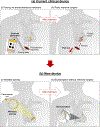
Extended Data Fig. 1 |. Illustrations that compare use scenarios of conventional temporary pacemakers and the bioresorbable, implantable, leadless, battery-free devices reported here.
a, Schematic illustration that demonstrates the existing clinical approach for using conventional temporary pacemakers. (i) An external generator connects through wired, percutaneous interfaces to pacing electrodes attached to the myocardium. Temporary transvenous leads are affixed to the myocardium either passively with tines or actively with extendable/retractable screws. (ii) The pacing leads can become enveloped in fibrotic tissue at the electrode-myocardium interface, which increases the risk of myocardial damage and perforation during lead removal. As a result, temporary epicardial leads placed at the time of open heart surgery are often cut and allowed to retract to avoid the risk of removal by traction. b, The proposed approach is uniquely enabled by the bioresorbable, leadless device introduced here. (i) Electrical stimulation paces the heart via inductive wireless power transfer, as needed throughout the post-operative period. (ii) Following resolution of pacing needs or insertion of a permanent device, the implanted device dissolves into the body, thereby eliminating the need for extraction.
Extended Data Fig. 2 |
Extended Data Fig. 2 |. Design of bioresorbable, implantable, leadless, battery-free cardiac pacemaker.
a, Dimensions of the device: (top) x,y-view; (bottom) x,z-view. The minimum length of the device is 15.8 mm. The total length can be altered to meet requirements for the target application, simply by changing the length of the extension electrode. b, Dimensions of the contact pad. PLGA encapsulation covers the top surface of the contact electrode to leave only the bottom of contact electrode exposed.
Extended Data Fig. 3 |
Extended Data Fig. 3 |. Modeling and experimental studies of mechanical reliability of the bioresorbable, leadless cardiac pacemaker.
a, Photograph (left) and FEA (right) results for devices during compressive buckling (20%). Scale bar, 10 mm. b, c, d, Photograph of twisted (180°) and bent (bend radius = 4 mm) devices. Scale bar, 10 mm. e, Output voltage of a device as a function of bending radius (left), compression (middle), and twist angle (right) at different distances between the Rx and Tx coils (black, 1 mm; red 6 mm). n = 3 independent samples.
Extended Data Fig. 4 |
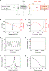
Extended Data Fig. 4 |. Electrical performance characteristics of the wireless power transfer system.
a, Schematic illustration of the circuit diagram for the transmission of RF power. Monophasic electrical pulses (programmed duration; alternative current) are generated by a waveform generator at ~13.5 MHz (Agilent 33250 A, Agilent Technologies, USA). The voltage can be further increased with an amplifier (210 L, Electronics & innovation, Ltd., USA). The generated waveforms (that is input power) are delivered to the Tx coil (3 turns, 20 mm diameter). This RF power is transferred to the Mg Rx coil (17 turns, 12 mm diameter) of an implanted bioresorbable cardiac pacemaker. The received waveform is transformed into a direct current output via the RF diode to stimulate the targeted tissue. b, Measured RF behavior of the stimulator (black, S11; red, phase). The resonance frequency is ~13.5 MHz. c, Simulation results for inductance (L) and Q factor as a function of frequency. d, An alternating current (sine wave) applied to the Tx coil. The resonance frequency and input voltage (that is transmitting voltage) are ~13.5 MHz and 7 Vpp, respectively. e, Example direct current output of ~13.2 V wirelessly generated via the Rx coil of the bioresorbable device. f, Output voltage as a function of transmitting frequency. At the resonance frequency (~13.5 MHz) of the receiver coil (transmitting voltage = 7 V), the device produces a maximum output voltage of ~13.2 V. g, Output voltage as a function of the distance between the Tx and Rx coils (transmitting voltage = 10 Vpp; transmitting frequency = ~13.5 MHz).
Fig. 1 |
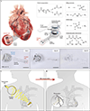
Fig. 1 |. Materials, design features and proposed utilization of a bioresorbable, implantable, leadless, battery-free cardiac pacemaker.
a, Left: schematic illustration of the device mounted on myocardial tissue. Middle: the electronic component is composed of three functional parts: (1) a wireless receiver, which consists of an inductive coil (W/Mg; thickness ~700 nm/~50 μm), a RF PIN diode (Si NM active layer, thickness 320 nm) and a dielectric interlayer (PLGA, thickness 50 μm) that acts as a power harvester and control interface; (2) flexible extension electrodes (W/Mg; thickness ~700 nm/~50 μm); and (3) a contact pad with exposed electrodes at the ends to interface with myocardial tissue (inset). A composite paste of W microparticles in Candelilla wax serves as an electrical interconnection. The entire system, excluding the contact pad, rests between two encapsulation layers of PLGA (thickness ~100 μm). Right: all components of the device naturally bioresorb via hydrolysis and metabolic action in the body. PLGA degrades into its monomers, glycolic and lactic acid, and the W/Mg electrode degrades into WOx and Mg(OH)2, respectively; the Si NM degrades into nontoxic Si(OH)4. Dissolution of Candelilla wax occurs by cleavage of the ester, anhydride and moieties via hydrolysis. b, Images of dissolution of a device associated with immersion in PBS (pH 7.4) at physiological temperature (37 °C). Scale bars, 10 mm. c, Schematic illustration of the wireless and battery-free operation of an implanted device via inductive coupling between an external transmission coil (Tx) and the receiver (Rx) coil on the device. d, Bioresorption subsequently eliminates the device after a period of therapy to bypass the need for device removal.
Fig. 2 |
Fig. 2 |. Ex vivo demonstrations of bioresorbable cardiac pacemakers on mouse and rabbit hearts and human cardiac tissue.
a–g, Bioresorbable cardiac pacemakers. Images of mouse (a) and rabbit (d) hearts and a human ventricular cardiac tissue slice (g). Positioning of the electrode of the bioresorbable pacemaker on the anterior ventricular myocardium (a,d) and on the surface of the human ventricular cardiac tissue slice (g). Scale bars, 10 mm. b,e,h, Far-field ECG recordings (b,e) and optical action potential maps (h) before (plain background) and during (shaded background; red arrowheads indicate delivered electrical stimuli) electrical stimulation using bioresorbable pacemakers. c,f,i, Activation maps of membrane potential for mouse (c), rabbit (f) and human myocardium (i) showing activation originating from the location of the electrode pad of the device, as indicated by the white arrows. Scale bars, 5 mm.
Fig. 3 |
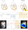
Fig. 3 |. Treatment of AV block using a bioresorbable, leadless cardiac pacemaker in an ex vivo Langendorff-perfused mouse model.
a, Schematic illustration of the nature of AV block and its treatment. In complete AV block, the conduction signal does not properly propagate from the atria to the ventricles. The pacemaker provides an electric impulse to restore activation of the ventricles. b, Far-field ECG monitoring of a mouse heart with second-degree AV block (plain background). Ventricular capture via electrical stimulation using a bioresorbable device, as shown in the far-field ECG signal (shaded background; red arrowheads indicate delivered electrical stimuli). Magnified insets illustrate a representative P-wave and QRS complex observed during second-degree AV block. c, Left: bright-field image of a mouse heart. The electrode of the bioresorbable pacemaker is positioned onto the anterior myocardial surface. Red and blue circles indicate the locations in the atria and ventricles (ven.), respectively, corresponding to the presented optical action potentials. Middle: simultaneous measurements of atrial and ventricular optical action potentials before stimulation (plain background) show asynchronous activation between the atria and ventricles indicating second-degree AV block. When electrical stimulation is delivered by the pacemaker (shaded background; red arrowheads indicate delivered electrical stimuli), the device restores activation of the ventricles. Right: activation map of the membrane potential during electrical stimulation by the device presents activation originating from the location of the contact pad, as indicated by the white arrow. Scale bars, 2 mm.
Fig. 4 |
Fig. 4 |. Demonstration of a bioresorbable, leadless cardiac pacemaker in an in vivo canine model.
a, Schematic diagram of the test setup. b, Photographs of an open-chest procedure with the device sutured to the ventricular epicardium (left) and a sutured incision after chest closure (right). Scale bars, 5 cm. c, Six-lead ECG recording of intrinsic rhythm (plain background, ~120 bpm) and ventricular capture (shaded background, ~200 bpm) using the device. n = 3 biologically independent animals per group. d, Time dependence of the output voltage generated by the device (30 V, 5 ms) and corresponding ECG recordings from the canine heart. e, Output voltage as a function of the distance between the Rx and Tx coils (transmitting voltage, 3.6 V). Different colors indicate three different sizes of Rx coil: black, 12 mm; red, 18 mm; blue, 25 mm. f, Output power as a function of the distance between the Rx and Tx coils (diameter of Rx coil, 25 mm; input frequency, 13.56 MHz; input power, 12 W; load resistance, 5,000 Ω). Different colors indicate three different designs for the Tx coils: black (solenoid type, four turns, 35-mm diameter); red (solenoid type, four turns, 100-mm diameter); blue (square, one turn, 260 × 280 mm2). g, In vivo closed chest canine model studies of maximum pacing distance (that is, the greatest distance between the two coils that enables consistent ventricular capture) as a function of transmitted (transm.) power (input frequency, 13.56 MHz). The tests used Tx coils III (square, one turn, 260 × 280 mm2) and an Rx coil with a diameter of 25 mm. n = 3 biologically independent animals per condition. g, Data are presented as mean ± s.e.m.
Fig. 5 |
Fig. 5 |. Implantation and operation of a bioresorbable, leadless cardiac pacemaker in a chronic in vivo rat model.
a, Surgical procedure for implantion of the device. The electrodes laminate onto the surface of the cardiac tissue, where they are sutured onto the anterior left ventricular myocardium. A small primary coil facilitates rapid testing of the functionality of the device. b, Schematic diagram of a wireless pacing system setup that supports operation across a cage environment. c, Spatially resolved wireless output voltage in a cage with an RF power of 2 W applied to the coils around the perimeter of the cage (load resistance (R), 5 kΩ; input frequency, 13.56 MHz). The output voltage of the bioresorbable pacemaker exceeds a threshold of 1 V regardless of the height and position of the device. d, ECG signals before (plain background) and during electrical stimulation (shaded background; red arrowheads indicate delivered electrical stimuli) with the implanted bioresorbable cardiac pacemaker for 4 days. n = 5 biologically independent animals.
Fig. 6 |
Fig. 6 |. Bioresorbability studies of the leadless cardiac pacemaker.
a, Three-dimensional-rendered CT images of rats collected over 7 weeks after the implantation of bioresorbable cardiac pacemakers. The images indicate the gradual disappearance of the devices to a stage where they are no longer visible on day 46. Scale bars, 10 mm. n = 3 biologically independent animals. b, Images of devices implanted in a rat model at different stages of bioresorption over the course of 4 weeks. The results reveal the mechanisms of bioresorption of the device after a therapeutic period. Scale bars, 5 mm. n = 3 biologically independent animals.
Fig. 7 |
Fig. 7 |. Biocompatibility and toxicity studies of a bioresorbable, leadless cardiac pacemaker.
a, Representative image of Masson’s trichrome staining of a cross-sectional area of the anterior left ventricle of a rat (left) without (0 weeks) and with an implanted device after (middle) 3 weeks and (right) 6 weeks near the site of implantation. n = 3 animals per group examined over three independent experiments. Scale bars, 1 mm. b, Percentage volume of myocytes (pink), interstitial space (white) and fibrosis (blue) in transmural cardiac cross-sections of rats without an implant, 3 weeks and 6 weeks following implantation. Kruskal–Wallis test: interstitial space: H(2), 0.08889, P= 0.9929; fibrosis: H(2), 6.489, P= 0.0107; myocytes: H(2), 5.956, P= 0.0250. Dunn’s multiple comparison test at a significance level of 0.05, P= 0.0338. n = 3 biologically independent animals per group. c, Weights of animals measured every 3 days following surgery show an initial decrease, as anticipated after a major surgery, but increase appropriately with age, as expected in healthy animals. n = 3 biologically independent animals per group. d, Absence of significant changes in ejection fraction in rats before device implantation (control) and 1 and 3 weeks after implantation demonstrates the preservation of mechanical cardiac function (paired data; Friedman’s test: χF2(2)=2.667, P= 0.3611. Dunn’s multiple comparison test at a significance level of 0.05). n = 3 biologically independent animals. e,f, Analysis of complete blood counts and blood chemistry for rats with and without device implantation reveals maintenance of overall healthy physiology in the animals. n = 3 biologically independent animals. Control data were provided by Charles River Laboratories. GLU, glucose; TRIG, triglycerides; ALT, alanine aminotransferase; AST, aspartate transaminase, ALP, alkaline phosphatase; CHOL, cholesterol; Cl, chloride; GGT, gamma-glutamyl transferase; Na, sodium; UREA, urea; PHOS, phosphorus; Ca, calcium; ALB, albumin; A/G, albumin/globulin; CREA, creatinine; GLOB, globulin; K, potassium; TBIL, total bilirubin; TP, total protein. b–f, Data are presented with error bars as means ± s.d.

Comment in

References

    1. Waldo AL, Wells JLJ, Cooper TB & MacLean WA Temporary cardiac pacing: applications and techniques in the treatment of cardiac arrhythmias. Prog. Cardiovasc. Dis. 23, 451–474 (1981). - PubMed
    1. Zoll PM et al. External noninvasive temporary cardiac pacing: clinical trials. Circulation 71, 937–944 (1985). - PubMed
    1. Curtis JJ et al. A critical look at temporary ventricular pacing following cardiac surgery. Surgery 82, 888–893 (1977). - PubMed
    1. Wilhelm MJ et al. Cardiac pacemaker infection: surgical management with and without extracorporeal circulation. Ann. Thorac. Surg. 64, 1707–1712 (1997). - PubMed
    1. Choo MH et al. Permanent pacemaker infections: characterization and management. Am. J. Cardiol. 48, 559–564 (1981). - PubMed

Publication types