. 2021 Jun 30;11(1):13591.
doi: 10.1038/s41598-021-93114-x.

Somatic inhibition by microscopic magnetic stimulation

Affiliations

Somatic inhibition by microscopic magnetic stimulation

Hui Ye et al. Sci Rep. .

Abstract

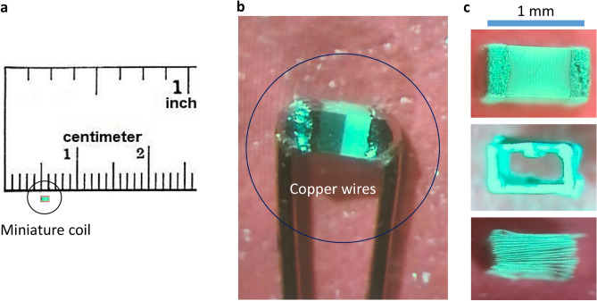
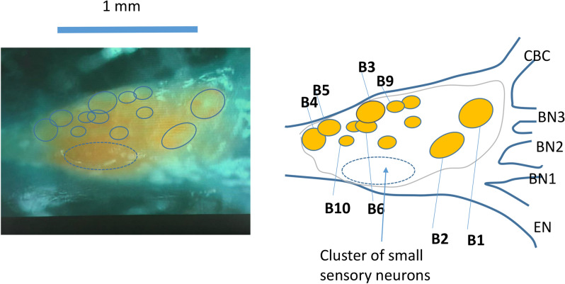
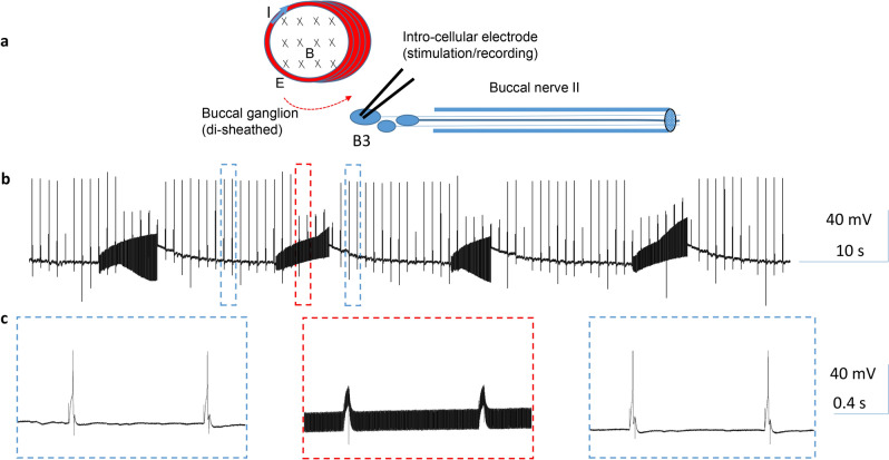
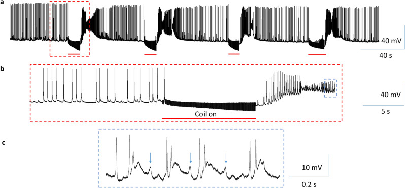
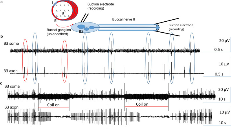
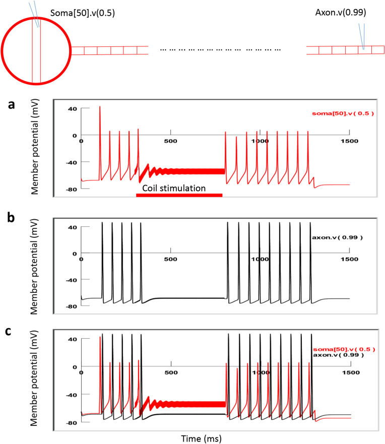
Electric currents can produce quick, reversible control of neural activity. Externally applied electric currents have been used in inhibiting certain ganglion cells in clinical practices. Via electromagnetic induction, a miniature-sized magnetic coil could provide focal stimulation to the ganglion neurons. Here we report that high-frequency stimulation with the miniature coil could reversibly block ganglion cell activity in marine mollusk Aplysia californica, regardless the firing frequency of the neurons, or concentration of potassium ions around the ganglion neurons. Presence of the ganglion sheath has minimal impact on the inhibitory effects of the coil. The inhibitory effect was local to the soma, and was sufficient in blocking the neuron's functional output. Biophysical modeling confirmed that the miniature coil induced a sufficient electric field in the vicinity of the targeted soma. Using a multi-compartment model of Aplysia ganglion neuron, we found that the high-frequency magnetic stimuli altered the ion channel dynamics that were essential for the sustained firing of action potentials in the soma. Results from this study produces several critical insights to further developing the miniature coil technology for neural control by targeting ganglion cells. The miniature coil provides an interesting neural modulation strategy in clinical applications and laboratory research.


Conflict of interest statement

The authors declare no competing interests.

Figures

Figure 1
Figure 1
The miniature coil used for the electrophysiology experiments. (a) The size of the coil was compared to a ruler. (b) The two leads of the coil were soldered to two copper wires for electric current delivery. (c) The internal structure of the coil was revealed by chemical removal of the ceramic cover. The coil contained 20 loops of fine wires in rectangular shape.
Figure 2
Figure 2
Anatomy of the buccal ganglion. Left picture shows one buccal ganglion. The right schematic was drawn based on the left picture. The picture and schematic together indicated the locations of several identified interneurons (B4 and B5), motor neurons (B3, B6, B9, B10) whose axons innervate buccal nerve 2 (BN2), and a cluster of small sensory neurons. EN: esophageal nerve. BN1: buccal nerve I; BN2: buccal nerve II. BN3: buccal nerve III. CBC: cerebro-buccal connection.
Figure 3
Figure 3
High-frequency magnetic stimulation inhibited buccal ganglion neurons firing at a low rate. (a) Experimental setup for the magnetic stimulation of the buccal neurons. The buccal ganglion was de-sheathed. An intracellular electrode was inserted into the B3 motor neuron for stimulation and recording. A miniature coil was positioned on top of the buccal ganglion for magnetic stimulation. I: electric current flow inside the coil. X: direction of the magnetic field generated by the coil current. Red arrow indicates the induced electric field by the coil. (b) Single action potentials were generated at 1 Hz by 4 ms current pulses delivered to the B3 soma. Coil stimulation reversibly suppressed these action potentials. (c) Expanded traces in (b).
Figure 4
Figure 4
High-frequency magnetic stimulation inhibited buccal ganglion neurons firing at a high rate. Position of the miniature coil was as in Fig. 3a. (a) A depolarization current was injected into the soma of the B3 neuron to elicit a train of high frequency (5–7 Hz) action potentials for approximately 10 s. Magnetic stimulation reversibly blocked these action potentials. (b) Expanded traces in (a).
Figure 5
Figure 5
High-frequency magnetic stimulation inhibited somatic neuron activity in a high K+ solution. Positon of the miniature coil was as in Fig. 3a. (a) Hyperactivity in the B3 neuron was elicited by high K+ Aplysia saline. 400 Hz stimulation by the miniature coil rapidly and reversibly eliminated the neuron activity. (b) Expended trace in (a). (c) Expanded trace in (b), showing increased excitatory events (arrows) after coil stimulation.
Figure 6
Figure 6
High-frequency magnetic stimulation on the soma inhibited functional output of the B3 motor neuron. (a) Experimental setup for the magnetic stimulation of the B3 neuron and assessment of its functional output. (b) Spontaneous B3 activity recorded in the soma and the axon demonstrated a one-to-one relationship. The soma action potential led the axonal action potential by approximately 6 ms. Hyperpolarization of the soma eliminated action potentials in both the soma and the axon. (c) Magnetic stimulation blocked spontaneous action potentials in the soma, leading to a suppressed activity in the distal axon.
Figure 7
Figure 7
Trans-sheath inhibition of the soma activity by the magnetic stimulation. (a) Experimental setup and orientation of the coil to the buccal ganglion. An extracellular electrode was positioned ganglion sheath, right above the soma of the B3 neuron in the un-disheathed buccal ganglion. Another suction electrode was applied to the distal end of the BN2. (b) One-to-one relationship between the soma and axon activities were observed in two neurons (blue and red circles). (c) Magnetic stimulation on the buccal ganglion eliminated the action potentials in both the soma and axon in both neurons.
Figure 8
Figure 8
The intensity of the electric field induced by the magnetic coil. (a) Distribution of the induced electric field around the coil in a 3D plot. (b) Distribution of the induced electric field around the coil in a 2D plot. (c) Induced electric field intensity as a function of the distance to the coil center at various voltage across the two ends of the coil. Different colors represented increased voltages in the coil (1–8 V). At 1 mm, the intensity of the E is approximately 20 V/m when the measured coil voltage is 2.16 V, the measured coil voltage for the electrophysiology experiments.
Figure 9
Figure 9
NEURON model for an Aplysia buccal neuron under miniature coil stimulation. The modeled neuron contained a spherical soma and a cylindrical axon. The soma sphere was 200 μm in diameter and was divided into 100 segments. The axon cylinder was 15 μm in diameter and 20,000 μm in length and was divided into 200 segments of equal length. Each neural compartment was modeled by H/H type ion channel mechanisms. The center of the soma was set to be (0, 0). The neuron was stimulated by a circular coil, whose center was located at (− 1000 µm, 300 µm). The radius of the coil was 250 μm. High frequency, biphasic electric pulses were delivered into the coil to induce electric field (E). I: coil current. X: direction of the magnetic flux when the coil current was increasing in a clockwise direction. Point A (x, 0) was an arbitrary point on the neuron, whose distance to the center of the coil is r in Eq. (2).
Figure 10
Figure 10
HFS with miniature magnetic coil inhibited soma activity and blocked neuron output in the modeled axon. The miniature coil was positioned at (− 1000, 300). A depolarization current was injected into the soma to trigger action potentials. A 500 ms train of biphasic square pulses (400 Hz) was applied to the coil, leading to the blockage of the action potentials in the soma. Activity recorded from the distal end of the axon was also eliminated. (a) Membrane potential recorded from the soma. (b) Membrane potential recorded from the distal axon. (c) Dual recording from the soma and the axon.
Figure 11
Figure 11
Ion channel dynamics underlying soma inhibition by high-frequency magnetic stimulation with the miniature coil. Membrane potential (a), Na+ current (b), K+ current (c), sodium channel activation m (d), sodium channel inactivation h (e) and potassium channel activation n (f) in the center of the soma (soma [50]) were plotted.

Similar articles

Cited by

References

    1. Habbema L, Neumann HA. Lidocaine: Local anaesthetic with systemic toxicity. Ned. Tijdschr. Geneeskd. 2008;152:1397. - PubMed
    1. Bhadra, N. & Kilgore, K. L. High-frequency nerve conduction block. in Conference proceedings: Annual International Conference of the IEEE Engineering in Medicine and Biology Society. IEEE Engineering in Medicine and Biology Society. Annual Conference, Vol. 7, 4729–4732. 10.1109/IEMBS.2004.1404309 (2004). - PubMed
    1. Bhadra N, Kilgore KL. High-frequency electrical conduction block of mammalian peripheral motor nerve. Muscle Nerve. 2005;32:782–790. doi: 10.1002/mus.20428. - DOI - PubMed
    1. Rosenbaum R, et al. Axonal and synaptic failure suppress the transfer of firing rate oscillations, synchrony and information during high frequency deep brain stimulation. Neurobiol. Dis. 2014;62:86–99. doi: 10.1016/j.nbd.2013.09.006. - DOI - PMC - PubMed
    1. Arle JE, Mei L, Carlson KW, Shils JL. High-frequency stimulation of dorsal column axons: Potential underlying mechanism of paresthesia-free neuropathic pain relief. Neuromodul. J. Int. Neuromodul. Soc. 2016;19:385–397. doi: 10.1111/ner.12436. - DOI - PubMed

Publication types