Review
. 2021 May 5;8(12):2100214.
doi: 10.1002/advs.202100214. eCollection 2021 Jun.

Recent Advances in Ligand Design and Engineering in Lead Halide Perovskite Nanocrystals

Affiliations
Review

Recent Advances in Ligand Design and Engineering in Lead Halide Perovskite Nanocrystals

Katie Hills-Kimball et al. Adv Sci (Weinh). .

Abstract

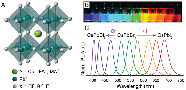
Lead halide perovskite (LHP) nanocrystals (NCs) have recently garnered enhanced development efforts from research disciplines owing to their superior optical and optoelectronic properties. These materials, however, are unlike conventional quantum dots, because they possess strong ionic character, labile ligand coverage, and overall stability issues. As a result, the system as a whole is highly dynamic and can be affected by slight changes of particle surface environment. Specifically, the surface ligand shell of LHP NCs has proven to play imperative roles throughout the lifetime of a LHP NC. Recent advances in engineering and understanding the roles of surface ligand shells from initial synthesis, through postsynthetic processing and device integration, finally to application performances of colloidal LHP NCs are covered here.

Keywords: device integration; ligand characterization; ligand engineering; nanocrystal surface design; optical and optoelectronic properties; perovskite nanocrystals; stability.


Conflict of interest statement

The authors declare no conflict of interest.

Figures

Figure 1
Figure 1
The LHP structure and tunable LHP NC optical properties. A) Schematic representation of the perovskite structure showing one corner‐sharing BX6 cuboctahedron housing an “A” cation. B) Pictures of colloidal solutions of perovskite NCs with varying halide compositions demonstrating the NC brightness and wide range of PL emissions and C) selected corresponding PL spectra. B,C) Adapted with permission.[ 43 ] Copyright 2015, American Chemical Society.
Figure 2
Figure 2
Ligand shell characterization. A) Molecular structure of oleylamine (OAm, left) and oleic acid (OA, right), the two most common ligands utilized in LHP NC synthesis. B) Schematic of the possible ligand–NC interactions in LHP NCs based on the precursors used in synthesis. A,B) Reproduced with permission.[ 84 ] Copyright 2016, American Chemical Society. C) 1H NMR spectra of as‐synthesized CsPbCl3 (black), CsPbBr3 (red), and CsPbI3 (blue) NCs. Peak numbering corresponds to the hydrogen atom numbering shown in (A). D) Zoomed in regions of the 1H NMR spectra shown in (C). C,D) Adapted with permission.[ 103 ] Copyright 2019, The Royal Society of Chemistry. E) NOESY spectrum of the ligand shell of CsPbBr3 NCs. Adapted with permission.[ 84 ] Copyright 2016, American Chemical Society. F) Solid‐state 133Cs spin echo and 2D 1H→133Cs CP‐HETCOR NMR spectra. Adapted with permission.[ 112 ] Copyright 2020, American Chemical Society. G) XPS spectra of the Br 3d peak for MAPbBr3 NCs compared to bulk. Red and blue dotted lines represent the fitting results of the spectra into two peaks. Adapted with permission.[ 45 ] Copyright 2015, American Chemical Society. H) Schematic representation of possible interactions of oleylammonium with the LHP surface. Oleylammonium can directly add to the surface or can substitute into the “A” cation sites. Adapted with permission.[ 113 ] Copyright 2017, American Chemical Society.
Figure 3
Figure 3
LHP NCs synthesis methods. A) Schematic representation of the LARP synthesis technique. B) Schematic representation of the hot injection synthesis technique.
Figure 4
Figure 4
Effects of OA and OAm ligands in LHP NC growth and assembly. A) PL QY comparison of CsPbBr3 NCs synthesized with alkylamine ligands of varying length (left) and their corresponding optical pictures under visible and UV light (right). Adapted with permission.[ 138 ] Copyright 2017, Elsevier. B) PL emission maxima as a function of concentration of added alkylamine in MAPbBr3 nanoplatelets synthesized with alkylamine ligands of varying carbon chain length. Increase of alkylamine resulted in a decrease of the number of unit cell layers in the LHP nanomaterials. Adapted with permission.[ 165 ] Copyright 2016, American Chemical Society. C) Schematic illustration of 1‐unit cell layer thick MAPbX3 perovskite nanoplatelets. Protonated alkylamines reside in “A” position sites restricting further growth in that direction. Reproduced with permission.[ 164 ] Copyright 2015, American Chemical Society. D) TEM image of CsPbBr3 nanosheets synthesized using a combination of short and long carbon chain alkylamines. (Scale bar is 1  µm). Reproduced with permission.[ 160 ] Copyright 2016, American Chemical Society. E) TEM image of CsPbBr3 nanowires synthesized through altering the ratios between alkyl carboxylic acids to alkylamines. (Scale bar is 200  nm). Reproduced with permission.[ 155 ] Copyright 2016, American Chemical Society. F) TEM image of CsPbBr3 supercrystals formed after 30 min synthesis time. Reproduced with permission.[ 183 ] Copyright 2018, Wiley‐VCH. G) Optical microscopy image of a large‐area self‐assembly of LHP NCs achieved through solvent evaporation. H) Photograph of the green PL of an assembly of LHP NC superlattices under UV illumination. G,H) Reproduced with permission.[ 184 ] Copyright 2018, Springer Nature.
Figure 5
Figure 5
Varying ligand identity in the synthesis of LHP NCs. A) PL emission intensity as a function of ethanol treatment time for TOPO‐capped CsPbBr3 NCs (green and red) versus traditional OA/OAm‐capped CsPbBr3 NCs (blue and black) produced at varying synthesis temperatures. Adapted with permission.[ 87 ] Copyright 2017, American Chemical Society. B) PL QY as a function of number of purification cycles with methyl acetate for octylphosphonic acid (OPA)‐capped CsPbBr3 (red) versus traditional OA/OAm‐capped CsPbBr3 NCs (blue). Inset shows lack of detectable change in PL emission of OPA‐capped CsPbBr3 NCs following multiple (8) rounds of purification. C,D) TEM images of the OPA‐capped CsPbBr3 NCs after 2 C) and 8 D) rounds of purification with methyl acetate. B–D) Reproduced with permission.[ 207 ] Copyright 2018, American Chemical Society. E) Schematic image of the tight binding afforded by synthesizing CsPbX3 NCs with zwitterionic ligands. F) PL QY of NCs capped with 3‐(N,N‐dimethyloctadecylammonio)propanesulfonate (green) versus traditional OA/OAm (black) after two rounds of purification with varying solvents after 1 day and 28 days of storage time. E,F) Adapted with permission.[ 88 ] Copyright 2018, American Chemical Society.
Figure 6
Figure 6
LHP NC encapsulation and templated growth synthetic strategies for enhanced NC stability. A) Laurionite‐type Pb(OH)Br encapsulation of reduced‐dimensional perovskite NCs. B–D) TEM images of perovskite@Pb(OH)Br core–shell microparticles formed using different volume ratios of OAm to OA (OA volume fixed to 75  µL). A–D) Reproduced with permission.[ 216 ] Copyright 2020, American Chemical Society. E) Schematic illustration of MAPbClxBr3− x NCs ligated with polymerizable ligands and the resulting crosslinked polymer network (top) and transparent MAPbClxBr3− x NC crosslinked polymer network disks (diameter = 3  cm) under visible (above) and UV (below) illumination for NCs with increasing bromide compositions (decreasing x) (bottom). Reproduced with permission.[ 217 ] Copyright 2018, American Chemical Society. F) Binding energy calculations for P2VP on an LHP NC surface with an increasing number of 2VP units. Inset shows a DFT simulation of a P2VP oligomer with four 2VP units on the LHP NC (100) surface. Adapted with permission.[ 232 ] Copyright 2017, American Chemical Society. G) SE–STEM and H) HAADF–STEM images of CsPbI3 NCs in mesoporous silica matrices with a 7 nm pore size. I) Photographs of CsPbBr3 NCs (top) and CsPbI3 NCs bottom embedded in mesoporous silica with a 7  nm pore size under visible (left) and UV (right) light. G–I) Reproduced with permission.[ 240 ] Copyright 2016, American Chemical Society.
Figure 7
Figure 7
Enhancement of NC properties through postsynthetic surface treatments. A) Absorption and emission of CsPbBr3 NCs before (black) and after (red) a surface treatment with a tetrafluoroborate salt showing ≈3x PL emission intensity enhancement. B) Photographs of CsPbX3 NCs under UV illumination before (above) and after (below) surface treatment with a tetrafluoroborate salt showing brighter NC emissions following treatment. A,B) Reproduced with permission.[ 93 ] Copyright 2018, American Chemical Society. C) Absorption and emission of untreated CsPbBr3 NCs (blue) and CsPbBr3 NCs that were treated with a thiocyanate salt (red) directly following synthesis (above) or after NC aging (below). Adapted with permission.[ 94 ] Copyright 2017, American Chemical Society. D) PL LT spectra of CsPbBr3 NCs before (red) and after (green) tetrafluoroborate treatment showing transition toward monoexponential decay behavior. Adapted with permission.[ 93 ] Copyright 2018, American Chemical Society. E,F) Charge density calculations using PBE0+SOC for CsPbBr3 with E) a single surface Br vacancy or F) two surface Br vacancies without (left) and with (right) 1,3‐adamantanedicarboxylic acid (ADA) passivation. Reproduced with permission.[ 266 ] Copyright 2019, Royal Society of Chemistry. G) Schematic illustration of the loss of PL intensity in CsPbI3 NCs due to the acid–base reaction between OA and OAm (right) and PL recovery upon introduction of TOP (left). H) PL intensity of CsPbI3 NCs versus time (black) and change in PL intensity following TOP treatment performed at differing stages of the aging process (red). G,H) Reproduced with permission.[ 275 ] Copyright 2020, American Chemical Society.
Figure 8
Figure 8
Postsynthetic encapsulation of LHP NCs. A) TEM image of the CsPbBr3/SiO2 Janus NCs (top) and elemental mapping results (bottom, scale bars = 10  nm). Reproduced with permission.[ 302 ] Copyright 2018, American Chemical Society. B) Photographs of POSS‐coated NC powders (left) and a POSS‐NC suspension in water after 10 weeks storage under UV light (right). Reproduced under the terms of a Creative CommonsAttribution 3.0 International License.[ 305 ] Copyright 2016, Royal Society of Chemistry. C,D) Central emission wavelength for different individual NCs embedded in C) PMMA and D) PS over time. Adapted with permission.[ 314 ] Copyright 2019, American Chemical Society. E) Schematic image of the swelling/deswelling process utilized for incorporating LHP NCs into PS microspheres. F) TEM images of the LHP NCs incorporated into polymer spheres. Reproduced with permission.[ 311 ] Copyright 2019, Wiley‐VCH.
Figure 9
Figure 9
Structural and morphological changes in LHP NCs following alteration of ligand ratio post synthesis. TEM image[ 321 ] A) and crystal structure schematic[ 319 ] B) of as‐synthesized CsPbBr3 NCs. TEM image[ 321 ] C) and crystal structure schematic[ 319 ] D) of lead‐depleted 0D Cs4PbBr6 NCs after phase transformation of CsPbBr3 upon addition of excess OAm. A,C) Reproduced with permission.[ 321 ] Copyright 2017, American Chemical Society. B,D) Reproduced with permission.[ 319 ] Copyright 2017, American Chemical Society. E) Absorption spectra evolution during transition from CsPbBr3 to Cs4PbBr6 and back through changing the ratio between OA and OAm. Adapted with permission.[ 321 ] Copyright 2017, American Chemical Society. F) TEM image of OA treated CsPbBr3 nanocubes which transformed into nanoplatelets. G,H) TEM images of CsPbBr3 nanocubes that were treated with small amounts of OAm to form nanowires. F–H) Reproduced with permission.[ 256 ] Copyright 2019, Springer.
Figure 10
Figure 10
Ligand role in ion exchange reactions. A) Reaction schematic for a quasi‐solid–solid cation exchange to achieve Mn2+‐doped CsPbCl3 NCs. B) 1H NMR of a colloidal solution of CsPbCl3 NCs with added OA or added OAm. Shift in α peak position followed a trend with added OA and added OAm. After adding ligands, the colloidal solution was dried for cation exchange. C–E) Resulting optical spectra following the solid‐state Mn2+ cation exchange with C) added OAm, D) no added ligands, and E) added OA. Mn–PL Ar. is the Mn–PL peak area normalized to the bandgap PL. F) Schematic image of the mechanism of the quasi‐solid–solid cation exchange which is controlled by altering ligand composition. A–F) Adapted with permission.[ 86 ] Copyright 2020, American Chemical Society. G) Schematic representation of “B” site cation exchange afforded through the use of metal carboxylate precursors, which could lead to the formation of Pb2+ vacancies through an anchoring mechanism. Adapted with permission.[ 346 ] Copyright 2019, American Chemical Society.
Figure 11
Figure 11
Ligand role in postsynthetic processing of LHP NCs. A) Schematic representation of nanoparticles self‐assembling to form a 1D peapod structure utilizing PbSO4‐oleate‐capped clusters. B) TEM image of CsPbBr3 NCs self‐assembled into the 1D peapod structure. A,B) Reproduced with permission.[ 349 ] Copyright 2016, American Chemical Society. C) Schematic representation of the electrophoretic deposition setup used to deposit PbSO4‐oleate‐capped CsPbBr3 NC peapods onto a TiO2 film. D) Low magnification SEM image of a hierarchical array of electrophoretically deposited PbSO4‐oleate‐capped CsPbI3 NC peapods. C,D) Reproduced with permission.[ 352 ] Copyright 2018, American Chemical Society. E) TEM image of nanoplatelets formed from putting CsPbBr3 NCs under pressure (inset shows TEM image of sample before nanoplatelets were dispersed in nonpolar solvent directly following pressure treatment). F) High resolution TEM image of a nanoplatelet formed during the pressure processing treatment. G) Schematic image of the pressure processing transformation process. NCs are first subjected to hydrostatic pressure, followed by formation of nanoplatelets through deviatoric stress‐induced permanent sintering during which ligands are detached and move toward the surface exposed areas of the NCs. E–G) Reproduced with permission.[ 358 ] Copyright 2017, Wiley‐VCH. H) Perovskite containing films (top) and drawings (bottom) made from combining LHP NCs with silicone resins. Reproduced with permission.[ 366 ] Copyright 2017, Royal Chemistry Society. I) Schematic image of ligand polymerization induced by mild plasma treatment. J) Schematic image of LHP NC film patterning through plasma treatment. K) photograph of red, green and blue NC‐dot array patterned on a 5 × 5 cm2 glass substrate. The diameter of each dot is 1  mm. I–​K) Reproduced with permission.[ 364 ] Copyright 2019, American Chemical Society.
Figure 12
Figure 12
LHP NCs in LEDs. A) Schematic image of the efficiency of charge injection and transport in LHP NC films formed with FAPbBr3 NCs passivated with short carbon chain (left) and long carbon chain (right) ligands. B) Schematic image of the LED device fabricated using FAPbBr3 NCs. C) EQE versus voltage of LEDs fabricated using FAPbBr3 NCs passivated with butylamine (black), hexylamine (red), and octylamine (blue). D) EL spectra of LEDs fabricated with butylamine‐passivated FAPbBr3 NCs at different applied biases. Inset shows an image of the LED device. A–D) Adapted with permission.[ 395 ] Copyright 2017, Elsevier. E) Schematic image of the ligand exchange process using quaternary alkylammonium halides. F) EQE versus current density for LEDs fabricated using CsPbBr3 NCs passivated with quaternary alkylammonium bromide ligands of varying carbon chain length. G) Photographs of thin films formed from CsPbBr3 NCs passivated with quaternary alkylammonium bromide ligands of varying length under UV illumination over time. E–G) Reproduced with permission.[ 400 ] Copyright 2019, American Chemical Society. H) Schematic image of a solid‐state ligand exchange (SLE) process to achieve benzoic acid and 4‐phenylbutylamine capped LHP NCs in the NC film. I) Luminance versus voltage for LHP NC‐based LED devices that underwent different SLE conditions. J) Current efficiency versus voltage for LHP NC‐based LED devices that underwent different SLE conditions. H–​J) Adapted with permission.[ 412 ] Copyright 2018, American Chemical Society. K) Cross‐sectional TEM image of a MAPbI3 thin film without 4‐fluorophenylmethylammonium iodide additives. L) Cross‐sectional TEM image of a MAPbI3 thin film with 4‐fluorophenylmethylammonium iodide additives showing in situ growth of MAPbI3 NCs during the film formation process. M) EQE versus current density of MAPbI3 LEDs with (red) and without (black) 4‐fluorophenylmethylammonium iodide additives. K–M) Adapted with permission.[ 419 ] Copyright 2017, American Chemical Society.
Figure 13
Figure 13
LHP NCs as photoexcited downshifting emitters in WLEDs. A) Luminous efficiency and PL intensity versus current for WLEDs fabricated with CsPbBr3 NCs that had undergone a ligand exchange with 1‐tetradecyl‐3‐methylimidazolium bromide. Adapted with permission.[ 197 ] Copyright 2020, Elsevier. B) CIE color coordinates of a WLED device fabricated from a blue LED chip and green and red silica‐coated CsPbBr3 and CsPb(Br/I)3 NCs, respectively (white circle) and the color triangle of the WLED device (red dashed line) compared to the NTSC TV standard (black dashed line). The inset shows the fabricated WLED. C) The PL spectra of the WLED fabricated in (B) at different operation times demonstrating enhanced stability. B,C) Adapted with permission.[ 218 ] Copyright 2016, Wiley‐VCH.
Figure 14
Figure 14
LHP NCs in solar cell devices. A) Schematic image of the changes in NC size and ligand coverage during purification treatments. B) Portion of the 1H NMR spectrum of CsPbBrI2 NCs during purification treatments shown in (A) exhibiting a decrease in ligand concentration. A,B) Reproduced with permission.[ 432 ] Copyright 2020, Wiley‐VCH. C) Energy level diagram of materials used in a solar cell fabricated using a short‐chain ligand‐passivated (propionic acid and butylamine) CsPbBr3 NC ink. D) Short circuit current and open‐circuit voltage versus number of deposition cycles of CsPbBr3 NC ink for the solar cell device structure shown in (C) Adapted with permission.[ 371 ] Copyright 2017, Nature Publishing Group. E) Schematic illustration of the CsPbI3 NC film formation process and AX salt treatment for solar cell device fabrication. F) Schematic cross section of a CsPbI3 NC‐sensitized solar cell overlaid on an SEM image of the cross‐section of the device. G) JV characteristics of CsPbI3 NC solar cell devices treated with FAI (pink), MAI (green), FABr (yellow), MABr (gray), CsI (dark blue), and a no‐additive control (light blue). E‐G) Adapted with permission.[ 436 ] Copyright 2017, AAAS. H) Contact angle measurement of a perovskite film without (above) and with (below) MAPbI3 NCs added to the top of the perovskite film. I) Schematic image of a solar cell device fabricated by adding MAPbI3 NCs to the top of the perovskite absorber layer. J) Contact angle measurement of a perovskite film without (above) and with (below) MAPbI3 NCs embedded within the film. K) Schematic image of a solar cell device fabricated by embedding MAPbI3 NCs into the perovskite absorber layer. H‐K) Reproduced with permission.[ 439 ] Copyright 2018, Royal Society of Chemistry.
Figure 15
Figure 15
A) Schematic image of the competing dynamic relaxation processes of CsPbCl3 NCs passivated with 3‐mercaptopropionic acid (MPA) for photodetector applications. B) Photocurrent versus time for photodetectors without (black) and with (red = 60  s and blue = 90  s) ligand exchange with MPA. A,B) Adapted with permission.[ 442 ] Copyright 2019, American Chemical Society. C) Schematic image of the formation of MAPbBr3 NCs in a Pb‐MOF matrix through the addition of MABr for use in encryption/decryption technologies. D) PL spectra demonstrating the on/off fluorescence of the MAPbBr3 NC @ Pb‐MOF composites through the addition of methanol (off) and MABr (on). E) PL intensity, peak position and FWHM of the fluorescent emission of MAPbBr3 NC @ Pb‐MOF composites versus on/off cycle number. F) Printed QR code (top) and butterfly (bottom) using the MAPbBr3 NC @ Pb‐MOF composites. C‐F) Reproduced with permission.[ 391 ] Copyright 2017, Nature Publishing Group. G) Low magnification SEM image of CsPbX3 NC @ microhemisphere composites to serve as luminescent probes in cell imaging. Inset shows a higher resolution SEM image of a single CsPbX3 NC @ microhemisphere composite. H) Fluorescence image of the CsPbX3 NC @ microhemisphere composites with varying halide compositions. Bright‐field I), fluorescent J), and bright‐field and fluorescence overlay K) images of macrophage (RAW 264.7) cells incubated with CsPbBr3 NC @ microhemisphere composites. (Scale bars = 15  µm). L) Cell viability versus concentration of CsPbBr3 NCs in the microhemispheres. Bright‐field M), fluorescence N), and a bright‐field and fluorescence overlay O) images of live macrophage cells incubated with a mixture of mixed‐halide CsPbX3 @ microhemispheres. (Scale bars = 20  µm). P) PL spectrum of the multiplexed emission of the CsPbX3 NC @ microhemisphere composites. Q) Fluorescence 2D barcode for the PL spectrum shown in (P) for optical coding. G–Q) Adapted with permission.[ 230 ] Copyright 2017, Wiley‐VCH.

Similar articles

Cited by

References

    1. Alivisatos A. P., Science 1996, 271, 933.
    1. Murray C., Norris D. J., Bawendi M. G., J. Am. Chem. Soc. 1993, 115, 8706.
    1. Talapin D. V., Lee J.‐S., Kovalenko M. V., Shevchenko E. V., Chem. Rev. 2010, 110, 389. - PubMed
    1. Burda C., Chen X., Narayanan R., El‐Sayed M. A., Chem. Rev. 2005, 105, 1025. - PubMed
    1. Yin Y., Alivisatos A. P., Nature 2005, 437, 664. - PubMed

LinkOut - more resources