. 2021 May 1;8(12):2100532.
doi: 10.1002/advs.202100532. eCollection 2021 Jun.

Magnetophoretic Decoupler for Disaggregation and Interparticle Distance Control

Affiliations

Magnetophoretic Decoupler for Disaggregation and Interparticle Distance Control

Hyeonseol Kim et al. Adv Sci (Weinh). .

Abstract

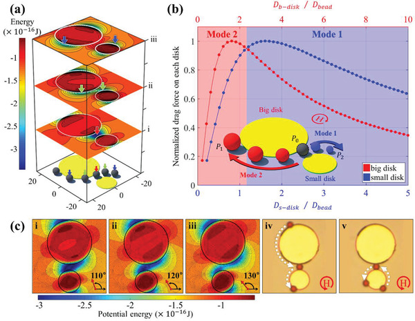
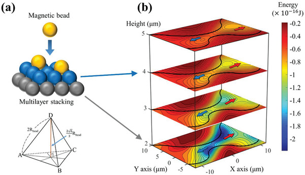
The manipulation of superparamagnetic beads has attracted various lab on a chip and magnetic tweezer platforms for separating, sorting, and labeling cells and bioentities, but the irreversible aggregation of beads owing to magnetic interactions has limited its actual functionality. Here, an efficient solution is developed for the disaggregation of magnetic beads and interparticle distance control with a magnetophoretic decoupler using an external rotating magnetic field. A unique magnetic potential energy distribution in the form of an asymmetric magnetic thin film around the gap is created and tuned in a controlled manner, regulated by the size ratio of the bead with a magnetic pattern. Hence, the aggregated beads are detached into single beads and transported in one direction in an array pattern. Furthermore, the simultaneous and accurate spacing control of multiple magnetic bead pairs is performed by adjusting the angle of the rotating magnetic field, which continuously changes the energy well associated with a specific shape of the magnetic patterns. This technique offers an advanced solution for the disaggregation and controlled manipulation of beads, can allow new possibilities for the enhanced functioning of lab on a chip and magnetic tweezers platforms for biological assays, intercellular interactions, and magnetic biochip systems.

Keywords: bead pair; decoupler; disaggregation; magnetic field; magnetophoresis; wave‐like pattern.


Conflict of interest statement

The authors declare no conflict of interest.

Figures

Figure 1
Figure 1
Proof of concept for “mode” switching of the bead: a) Magnetic potential energy distribution around the two disks under the rotating magnetic field of 90°, 130°, and 170°. The magnetic beads move along the disk boundary along with the direction of the magnetic field owing to the location of the potential energy minima, as shown in blue. Here, the potential minima move during field rotation, where the beads located (colored arrows) split into two and moves in the opposite direction along with each disk (i–iii). b) Change of the drag force according to the ratio between the diameter of each disk (red: big disk and blue: small disk) pattern and the bead. The big disk is fixed at twice size of the small disk ( D b − disk =  2  × D s − disk). When the small disk is more than 1.2 times the bead diameter, the beads moves toward the smaller disk, otherwise they move towards the big disk. The inset illustrates the two paths for bead movement when the beads were placed at the initial position (P 0) between the different sizes of disk (DSD) patterns (“Mode 1” to P 1 and “Mode 2” to P 2). c) Angular variation of the magnetic potential energy for the disk patterns with diameters of 15 and 30 µm with a 4 µm gap for 4.5 µm bead movement. ci–iii) Detailed angular variation of the simulated potential energies. The overlapped minimum energy for the two disks is split into two minima from a field angle of 130°, where the energy barrier is formed near big disk. Thus, the bead moves to the small disk (the dark blue represents the lower energy). civ,v) Because the small disk's size ratio (D s − disk /D bead  =  3.33), according to the graph in (a), the bead always experiences a large attractive force towards the small disk irrespective of their initial starting point. civ) Experimental observation showing motion in the “Mode 1" during which the beads starting from the big disk are directed to the small disk. cv) Experimental observation showing a motion in “Mode 1” during which a bead starting from the small disk is directed back to it.
Figure 2
Figure 2
Different movements of the bead according to the form of the controlled potential barrier by adjusting the gap size: If a horizontal (D gap  /D bead  > 1.4) or vertical (D gap  /D bead  < 0.8) barrier is formed between wells, the bead does not exhibit “mode” switching. ai) In the case of the horizontal barrier, the beads at each wave pattern moves without “mode” switching. aii) Schematic of the movement of the bead on a wave‐like pattern. aiii) Good agreement between the experimental observations and simulated results. The red and blue arrows represent the directions of the bead movement. bi) “Mode” switching occurs only if there is a single well without a potential barrier (D gap /D bead  =  0.8  − 1.4). bii) Schematic of the “mode” switching of beads on a wave‐like pattern, where “P 0” is the initial position of the bead. biii) Experimental observations of “mode” switching is consistent with simulation results. The red and blue arrows represent the directions of the movement of the bead. ci) In the case of a vertical barrier, the bead cannot cross the gap, is trapped, and rotates repeatedly in the track in which it is trapped. cii) Schematic representation of bead trapping and rotation on the wave‐like pattern. ciii) Experimental confirmation of bead trapping and rotation on the track.
Figure 3
Figure 3
Potential energy distribution according to the vertical distance assuming that beads are stacked in multilayer: a) Concept of beads being stacked in a multilayer. In the absence of a magnetic field, the beads are stacked in the form of a tetrahedron, and the distance between the first and second layers is 263Rbead. The vertical height of the bead on the first layer is the sum of the radius of the bead (R bead) and the thickness of the passivation layer (t p). The vertical height of the next layer should be the sum of the first layer and the distance between layers (263Rbead). b) Potential energies for bead layers with different vertical height. The depth of the energy well varies depending on the center of the bead at each layer, but it can be seen that wells are created and moved in opposite directions around the gap irrespective of vertical height. Hence, disaggregation can be achieved regardless of the vertical height because eventually, only a single layer structure or single bead remains on the 2D surface.
Figure 4
Figure 4
Disaggregation and movement of bead near decoupler with wave‐like pattern: a) Movement of disaggregated single beads and aggregated beads on the wave‐like patterns for different sizes and gaps of the decoupler, where the beads can go to the next decoupler. b) Angular dependence of the simulated forces of aggregated beads. The beads are clustered at one point due to a potential well between field angles of 60° and 120°. It is assumed that the magnetic moment of each bead rotates along the external magnetic field, and the x‐component of the magnetic force due to the potential energy generated at each bead position indicates that the bead 2 (with negative force) moves to the left (−x‐direction) and bead 1 and bead 3 (with positive force) moves to the right (+ x‐direction) in angle zone A. c) The sequential disaggregation process of aggregated beads into single beads. i) Disaggregation of single from clustered beads and motion in the −x‐direction for single beads along the lower track and in the + x‐direction along the upper track for two beads. ii) Disaggregation of individual beads and motion in the −x‐direction along the lower track (“Mode 1”) and in the + x‐direction along the upper track (“Mode 2”). iii) A single bead crosses the gap (decoupler 3) and eventually navigates in the −x‐direction.
Figure 5
Figure 5
Directional movement of single magnetic beads on the wave‐like pattern: a) The aggregated magnetic beads are split into single beads by the serial decoupler and then eventually move in the −x‐direction. The detached beads move to the adjacent decoupler in time intervals of 12f, 1f, etc. b) Change in the number of beads at the crest of a small wave at t  =  0, 12f, 1f, that is, after integers of half cycles of the field. The green color indicates the gap of the decoupler where the two waves meet. The beads are split in the decoupler and all the single beads move only in the −x‐direction under the rotating magnetic field. The number in bold on the diagram is the disaggregation process of the beads tracked by a white circle in Figure 5a. (The condition is highlighted in green in Table S2, Supporting Information.)
Figure 6
Figure 6
Interparticle distance control during the aggregation and disaggregation of pairs of magnetic beads: a) Schematic representation of the adjustment of the bead spacing by changing the field angle of applied field from 60° to 120° (indicated in blue in Table S2, Supporting Information). b) Bead translocation along the wave‐like pattern when the external magnetic field rotates from 0° to 180°. c) Change in the interparticle distance between beads was measured for the angle change of 5.81°. The distance is linearly adjusted except for the areas where the beads are in contact with each other (angle from 61.88° to 118.13°). The experimental results and calculations are in good agreement, confirming that the potential well begins to go away from 120°.
Figure 7
Figure 7
Selective control of magnetic/nonmagnetic beads by dual positive and negative magnetophoretic patterns: After filling the outer space of the 2D surface pattern with magnetic fluid, the condition for negative magnetophoresis is satisfied to reproduce all the preceding experiments for nonmagnetic polymer beads. For the simultaneous and selective control of magnetic beads and polymer beads, the surface patterning was designed so that the magnetic pattern and the cavity shape were repeated continuously on the 2D surface and vertically symmetric with each other. This design has affirmed the simultaneous disaggregation of aggregated magnetic and nonmagnetic beads under a rotating magnetic field in the same direction and presents the possibility of moving a single bead in different directions. However, in this case, the polymer beads could be moved only under the high external field of 900 Oe at 0.2% of ferrofluid concentration, unlike the magnetic beads designed to operate at 120 Oe.

Similar articles

Cited by

References

    1. Zhang S., Zhang R., Wang Y., Onck P. R., Den Toonder J. M. J., ACS Nano 2020, 14, 10313. - PMC - PubMed
    1. Pamme N., Lab Chip 2006, 6, 24. - PubMed
    1. Lim B., Vavassori P., Sooryakumar R., Kim C., J. Phys. D: Appl. Phys. 2017, 50, 033002.
    1. El‐Ali J., Sorger P. K., Jensen K. F., Nature 2006, 442, 403. - PubMed
    1. Abonnenc M., Borgatti M., Fabbri E., Gavioli R., Fortini C., Destro F., Altomare L., Manaresi N., Medoro G., Romani A., Tartagni M., Monaco E. L.o, Giacomini P., Guerrieri R., Gambari R., J. Immunol. 2013, 191, 3545. - PubMed

Publication types

LinkOut - more resources