Review
. 2021 Jun 17:2021:8790143.
doi: 10.1155/2021/8790143. eCollection 2021.

3D Electrospun Nanofiber-Based Scaffolds: From Preparations and Properties to Tissue Regeneration Applications

Affiliations
Review

3D Electrospun Nanofiber-Based Scaffolds: From Preparations and Properties to Tissue Regeneration Applications

Shanshan Han et al. Stem Cells Int. .

Abstract

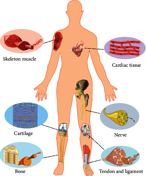
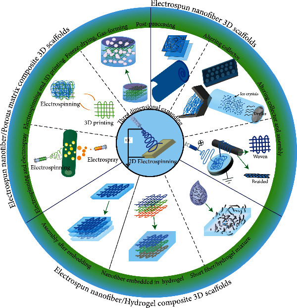
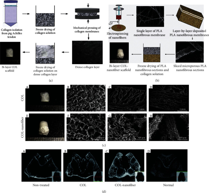
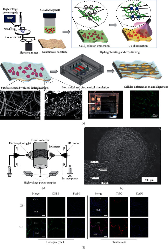
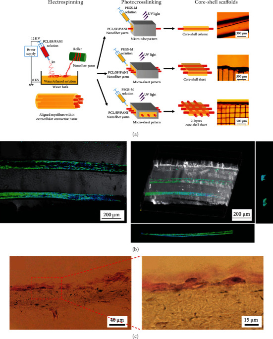
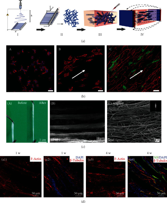
Electrospun nanofibers have been frequently used for tissue engineering due to their morphological similarities with the extracellular matrix (ECM) and tunable chemical and physical properties for regulating cell behaviors and functions. However, most of the existing electrospun nanofibers have a closely packed two-dimensional (2D) membrane with the intrinsic shortcomings of limited cellular infiltration, restricted nutrition diffusion, and unsatisfied thickness. Three-dimensional (3D) electrospun nanofiber-based scaffolds can provide stem cells with 3D microenvironments and biomimetic fibrous structures. Thus, they have been demonstrated to be good candidates for in vivo repair of different tissues. This review summarizes the recent developments in 3D electrospun nanofiber-based scaffolds (ENF-S) for tissue engineering. Three types of 3D ENF-S fabricated using different approaches classified into electrospun nanofiber 3D scaffolds, electrospun nanofiber/hydrogel composite 3D scaffolds, and electrospun nanofiber/porous matrix composite 3D scaffolds are discussed. New functions for these 3D ENF-S and properties, such as facilitated cell infiltration, 3D fibrous architecture, enhanced mechanical properties, and tunable degradability, meeting the requirements of tissue engineering scaffolds were discovered. The applications of 3D ENF-S in cartilage, bone, tendon, ligament, skeletal muscle, nerve, and cardiac tissue regeneration are then presented with a discussion of current challenges and future directions. Finally, we give summaries and future perspectives of 3D ENF-S in tissue engineering and clinical transformation.


Conflict of interest statement

The authors declare no conflict of interest.

Figures

Figure 1
Figure 1
Illustration of typical tissues with fibrous structures whose regeneration can be mediated by 3D ENF-S.
Figure 2
Figure 2
The summary of representative design approaches of 3D ENF-S.
Figure 3
Figure 3
3D electrospun nanofiber-based scaffolds for cartilage tissue regeneration. (a) The schematic illustration for fabrication and crosslinking of electrospun nanofiber porous 3D scaffold (3DS-1) and crosslinked with hyaluronic acid scaffold (3DS-2). (b) The porous and fibrous structure of uncrosslinked (A, E), heat-treated (B, F), crosslinked 3DS-1 group (C, G), and 3DS-2 group (D, H). (c) Collagen type II and aggrecan immunohistochemical staining results of nontreated, 3DS-1, and 3DS-2 scaffolds after in vivo implantation for 12 weeks. Reproduced with permission from [115]. Copyright © 2021, American Chemical Society. (d) Conventional electrospinning formed dense nanofiber membrane. Cryoelectrospinning (on a mandrel collector at -78°C) induced 3D porous PCL scaffold due to the ice crystal formation. (e) Hydrogel/nanofiber composite constructs exhibited good chondrogenic ECM deposition and higher stability than pure hydrogel scaffold in vitro cell culture and in vivo implantation. Reproduced with permission from [52]. Copyright © 2021, WILEY-VCH Verlag GmbH & Co. KGaA, Weinheim.
Figure 4
Figure 4
Electrospun nanofiber/hydrogel 3D scaffolds for bone tissue regeneration. (a) Schematic diagram of the experimental steps and the structure of 3D cell-laden hybrid scaffolds. (b) SEM micrographs of surface and cross-section of the freeze-dried hybrid scaffold. (c) Gross appearance of Alizarin Red staining and mineral quantification of hybrid scaffolds after incubation in SBF at 37°C for specific periods (mean ± SD of six replicates). Reproduced with permission from [124]. Copyright © 2016, Elsevier B.V.
Figure 5
Figure 5
Electrospun PLA nanofiber/freeze-dried collagen bilayer composite scaffold for osteochondral tissue engineering. (a) The fabrication process of freeze-dried collagen bilayer scaffolds and (b) nanofiber/freeze-dried collagen bilayer composite scaffolds, and (c) their microstructures. (d) Architecture evaluation of the repaired tissues after 12 weeks of implantation by μ-CT images ((A) nontreated group, (B) freeze-dried collagen bilayer scaffold group, (C) nanofiber/freeze-dried collagen bilayer composite scaffold group, and (D) normal joints). There were abundant subchondral bones formed in the nanofiber-collagen porous scaffold group. Adapted with permission from [84]. Copyright © 2013, Acta Materialia Inc. Published by Elsevier Ltd.
Figure 6
Figure 6
3D electrospun nanofiber-based scaffolds for tendon and ligament regeneration. (a) Schematic illustration of fabrication and stimulation of composite scaffold consisted of electrospun nanofibers and cell-laden hydrogel coating crosslinked by Ca2+ and UV light. Reproduced with permission from [129]. Copyright © 2019, American Chemical Society. (b) Electrospinning equipment for fabrication of silk fibroin-PCL nano/microfiber mat. (c) SEM images of cell-laden fiber/hydrogel 3D composite construct (cross-section). (d) Immunofluorescent staining of collagen type I and tenascin-C in the hybrid constructs. Scale bar = 200 μm. Copyright [130].
Figure 7
Figure 7
Nanofiber yarn/hydrogel composite 3D scaffolds for myoblast alignment and differentiation. (a) Preparation illustration of yarn/hydrogel composite 3D scaffolds with native skeletal muscle mimicking core-shell structure (aligned nanofiber yarns by electrospinning and PEG-based hydrogel shell via photocrosslinking). (b) Highly organized C2C12 myotubes within the 3D hydrogel. (c) H&E staining images of the construct with C2C12 cell encapsulation after cultivation for seven days. Reproduced with permission from [133]. Copyright © 2015, American Chemical Society.
Figure 8
Figure 8
Electrospun nanofibers in 3D scaffolds and their effects on cell alignment and neural differentiation. (a) A schematic illustration of the fabrication process of Anisogel. Electrospinning of aligned fibers (step I). Short fibers forming by cryosectioning (step II). Randomly oriented short fibers mixed within the hydrogel precursor solution before gelation and applying the magnetic field (step III). Fiber orientation under low magnetic field and hydrogel crosslinking result in the Anisogel (step IV). (b) The ability of the Anisogel to direct cell growth. (A) Fibroblasts mixed within a fibrin gel without fibers, (B) fibroblasts mixed within a fibrin gel with short oriented fibers, and (C) fibroblasts elongate in the direction of the oriented fibers. Scale bars 50 μm. Reproduced with permission from [80], Copyright © 2017, WILEY-VCH Verlag GmbH & Co. KGaA, Weinheim. (c, A) Electrospun-aligned fibrillar fibrin hydrogel with good flexibility. (B, C) Hierarchically aligned microstructure at different magnifications. (d) Immunofluorescence staining images of the longitudinal tissue section from the T8–T10 spinal cord segment at 1 and 4 weeks after scaffold implantation. Reused with permission from [149]. Copyright © 2016, Royal Society of Chemistry.
Figure 9
Figure 9
Nanofiber yarn/hydrogel composite 3D scaffolds with alignment, conductivity, and anisotropy for cardiac tissue engineering. Schematic illustration of (a) PCL/SF/CNT nanofiber yarns prepared by wet-dry electrospinning and (b) NFYs-NET scaffolds fabricated by a weaving technique. (c) 3D composite scaffold fabricated via encapsulating two layers of NFYs-NET with orthogonal orientation within UV crosslinked GelMA hydrogel (i). F-Actin (green) staining of CMs cultured on the NFYs-NET layer with horizontal direction (iii) and vertical direction (iv) within a 2-layer 3D scaffold. (d) Coculture of CMs and ECs within yarn/hydrogel 3D composite scaffolds. CMs were cultured on the NFYs-NET layer while ECs with green fluorescent protein were encapsulated within a hydrogel shell. Reproduced with permission from [67]. Copyright © 2017, American Chemical Society.

Similar articles

Cited by

References

    1. Griffith L. G., Naughton G. Tissue engineering--current challenges and expanding opportunities. Science. 2002;295(5557):1009–1014. doi: 10.1126/science.1069210. - DOI - PubMed
    1. Li X., Sun Q., Li Q., Kawazoe N., Chen G. Functional hydrogels with tunable structures and properties for tissue engineering applications. Frontiers in Chemistry. 2018;6 doi: 10.3389/fchem.2018.00499. - DOI - PMC - PubMed
    1. Guimarães C. F., Gasperini L., Marques A. P., Reis R. L. The stiffness of living tissues and its implications for tissue engineering. Nature Reviews Materials. 2020;5(5):351–370. doi: 10.1038/s41578-019-0169-1. - DOI
    1. Hollister S. J. Porous scaffold design for tissue engineering. Nature Materials. 2005;4(7):518–524. doi: 10.1038/nmat1421. - DOI - PubMed
    1. Ma L., Gao C., Mao Z., et al. Collagen/chitosan porous scaffolds with improved biostability for skin tissue engineering. Biomaterials. 2003;24(26):4833–4841. doi: 10.1016/S0142-9612(03)00374-0. - DOI - PubMed

LinkOut - more resources