. 2021 Jul 9;12(1):4238.
doi: 10.1038/s41467-021-24409-w.

Peta-bit-per-second optical communications system using a standard cladding diameter 15-mode fiber

Affiliations

Peta-bit-per-second optical communications system using a standard cladding diameter 15-mode fiber

Georg Rademacher et al. Nat Commun. .

Abstract

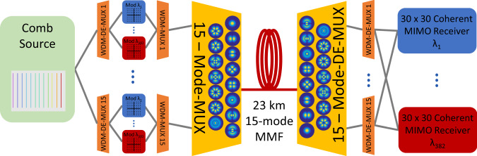
Data rates in optical fiber networks have increased exponentially over the past decades and core-networks are expected to operate in the peta-bit-per-second regime by 2030. As current single-mode fiber-based transmission systems are reaching their capacity limits, space-division multiplexing has been investigated as a means to increase the per-fiber capacity. Of all space-division multiplexing fibers proposed to date, multi-mode fibers have the highest spatial channel density, as signals traveling in orthogonal fiber modes share the same fiber-core. By combining a high mode-count multi-mode fiber with wideband wavelength-division multiplexing, we report a peta-bit-per-second class transmission demonstration in multi-mode fibers. This was enabled by combining three key technologies: a wideband optical comb-based transmitter to generate highly spectral efficient 64-quadrature-amplitude modulated signals between 1528 nm and 1610 nm wavelength, a broadband mode-multiplexer, based on multi-plane light conversion, and a 15-mode multi-mode fiber with optimized transmission characteristics for wideband operation.


Conflict of interest statement

The authors declare no competing interests.

Figures

Fig. 1
Fig. 1. Schematic diagram of the optical transmission system.
A total of 382 laser lines were generated by an optical comb source to generate 15 × 382 independent dual-polarization 64-QAM data signals. Each set of 382 WDM signals was spatially multiplexed on a different fiber mode and jointly transmitted over a 15-mode fiber. After spatial de-multiplexing, each spatial super-channel, formed by the 15 spatial channels of the same wavelength, was received by a 30 × 30 coherent MIMO receiver.
Fig. 2
Fig. 2. Mode-multiplexer based on multi-plane light conversion.
a Principle of the mode-multiplexer: 15 input beams from 15 single-mode fibers are reflected 15 times between phase masks and a dielectric mirror to form orthogonal modes that can be guided by the 15-mode fiber. b Measured wavelength-dependent loss of one mode-multiplexer. c Photograph of one mode-multiplexer.
Fig. 3
Fig. 3. 15-mode transmission fiber.
a Refractive index profile of the trench-assisted, graded-index 15-mode fiber. b Photograph of the fiber’s cross-section. c Camera recording of the output mode intensity profiles after 7.6 km 15-mode fiber when excited with ASE noise of 40 nm bandwidth. Only one mode is shown per mode group, as all modes within one mode group have equal intensity patterns. Different numbers of radial intensity maxima confirm a strong mode group selectivity of mode-multiplexer and fiber. d Wavelength-dependent attenuation measurements of the 23 km long 15-mode fiber. The fifth mode group has a higher attenuation, attributed to increased micro-bending sensitivity.
Fig. 4
Fig. 4. Wavelength dependence of the linear transmission properties.
a Intensity impulse responses of two wavelength channels. b Impulse response durations for all 382 wavelength channels. c Modal power coupling matrix for the wavelength channel at 1550 nm. d Mode-dependent loss (MDL) for all 382 wavelength channels after transmission and for selected wavelength channels in a back-to-back setup and with mode-multiplexers only.
Fig. 5
Fig. 5. Wavelength dependence of the signal quality after transmission.
The data rate of each of the 382 spatial super-channels was estimated by an implemented coding scheme and from generalized mutual information (GMI). The C-band performed overall better compared to the L-band due to a combination of reduced mode-dependent loss and phase-noise from the comb source.
Fig. 6
Fig. 6. Laboratory implementation of the transmitter setup.
The output of the comb source was modulated in two sub-systems, one for a high-quality tunable test-band and one for dummy channels. Fifteen de-correlated copies of the signal were generated in a split-and-delay stage to emulate independent data channels in each fiber mode.
Fig. 7
Fig. 7. Laboratory implementation of the 15-mode receiver.
a Groups of three output ports from the mode de-multiplexer were combined in power couplers after delaying two ports by 16.66 and 33.33 μs, respectively. This enabled the reception of all 15 output ports in five coherent receiver sub-systems that contained optical bandpass filters to select a WDM channel under test, EDFAs and a common local oscillator laser. Symbol definitions as in Fig. 6. b Schematic description of the 3 × 1 time-division multiplexing receiver concept.

References

    1. Richardson DJ, Fini JM, Nelson LE. Space-division multiplexing in optical fibres. Nat. Photonics. 2013;7:354–362. doi: 10.1038/nphoton.2013.94. - DOI
    1. Essiambre RJ, Kramer G, Winzer PJ, Foschini GJ, Goebel B. Capacity limits of optical fiber networks. J. Light. Technol. 2010;28:662–701. doi: 10.1109/JLT.2009.2039464. - DOI
    1. Winzer PJ, Neilson DT. From scaling disparities to integrated parallelism: a decathlon for a decade. J. Light. Technol. 2017;35:1099–1115. doi: 10.1109/JLT.2017.2662082. - DOI
    1. Google. A quick hop across the pond: supercharging the dunant subsea cable with SDM technology. https://cloud.google.com/blog/products/infrastructure/a-quick-hop-across... (2019).
    1. Ryf, R. et al. Coupled-core transmission over 7-core fiber. In Optical Fiber Communication Conference. Th4B–3 (2019).