

Development of a Low-Cost EEG-Controlled Hand Exoskeleton 3D Printed on Textiles
- PMID: 34248478
- PMCID: PMC8267155
- DOI: 10.3389/fnins.2021.661569
Development of a Low-Cost EEG-Controlled Hand Exoskeleton 3D Printed on Textiles
Abstract
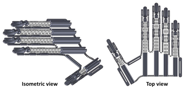
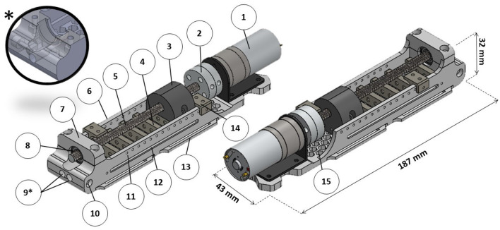
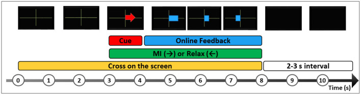
Stroke survivors can be affected by motor deficits in the hand. Robotic equipment associated with brain-machine interfaces (BMI) may aid the motor rehabilitation of these patients. BMIs involving orthotic control by motor imagery practices have been successful in restoring stroke patients' movements. However, there is still little acceptance of the robotic devices available, either by patients and clinicians, mainly because of the high costs involved. Motivated by this context, this work aims to design and construct the Hand Exoskeleton for Rehabilitation Objectives (HERO) to recover extension and flexion movements of the fingers. A three-dimensional (3D) printing technique in association with textiles was used to produce a lightweight and wearable device. 3D-printed actuators have also been designed to reduce equipment costs. The actuator transforms the torque of DC motors into linear force transmitted by Bowden cables to move the fingers passively. The exoskeleton was controlled by neuroelectric signal-electroencephalography (EEG). Concept tests were performed to evaluate control performance. A healthy volunteer was submitted to a training session with the exoskeleton, according to the Graz-BCI protocol. Ergonomy was evaluated with a two-dimensional (2D) tracking software and correlation analysis. HERO can be compared to ordinary clothing. The weight over the hand was around 102 g. The participant was able to control the exoskeleton with a classification accuracy of 91.5%. HERO project resulted in a lightweight, simple, portable, ergonomic, and low-cost device. Its use is not restricted to a clinical setting. Thus, users will be able to execute motor training with the HERO at hospitals, rehabilitation clinics, and at home, increasing the rehabilitation intervention time. This may support motor rehabilitation and improve stroke survivors life quality.
Keywords: 3D printing; brain-machine interface; hand exoskeleton; post-stroke; rehabilitation; soft robotics; textiles.
Copyright © 2021 Araujo, Silva, Netto, Morya and Brasil.
Conflict of interest statement
The authors declare that the research was conducted in the absence of any commercial or financial relationships that could be construed as a potential conflict of interest.
Figures


Similar articles
-
Induction of Neural Plasticity Using a Low-Cost Open Source Brain-Computer Interface and a 3D-Printed Wrist Exoskeleton.Sensors (Basel). 2021 Jan 15;21(2):572. doi: 10.3390/s21020572. Sensors (Basel). 2021. PMID: 33467420 Free PMC article.
-
Design of a 3D Printed Soft Robotic Hand for Stroke Rehabilitation and Daily Activities Assistance.IEEE Int Conf Rehabil Robot. 2019 Jun;2019:65-70. doi: 10.1109/ICORR.2019.8779449. IEEE Int Conf Rehabil Robot. 2019. PMID: 31374608
-
Testing of a 3D printed hand exoskeleton for an individual with stroke: a case study.Disabil Rehabil Assist Technol. 2021 Feb;16(2):209-213. doi: 10.1080/17483107.2019.1646823. Epub 2019 Aug 6. Disabil Rehabil Assist Technol. 2021. PMID: 31385727 Free PMC article.
-
An overview of robotic/mechanical devices for post-stroke thumb rehabilitation.Disabil Rehabil Assist Technol. 2018 Oct;13(7):683-703. doi: 10.1080/17483107.2018.1425746. Epub 2018 Jan 15. Disabil Rehabil Assist Technol. 2018. PMID: 29334274 Review.
-
Robotic devices and brain-machine interfaces for hand rehabilitation post-stroke.J Rehabil Med. 2017 Jun 28;49(6):449-460. doi: 10.2340/16501977-2229. J Rehabil Med. 2017. PMID: 28597018 Review.
Cited by
-
A review on EMG/EEG based control scheme of upper limb rehabilitation robots for stroke patients.Heliyon. 2023 Jul 20;9(8):e18308. doi: 10.1016/j.heliyon.2023.e18308. eCollection 2023 Aug. Heliyon. 2023. PMID: 37533980 Free PMC article. Review.
-
Intention Detection Strategies for Robotic Upper-Limb Orthoses: A Scoping Review Considering Usability, Daily Life Application, and User Evaluation.Front Neurorobot. 2022 Feb 21;16:815693. doi: 10.3389/fnbot.2022.815693. eCollection 2022. Front Neurorobot. 2022. PMID: 35264940 Free PMC article.
-
A Brain-Controlled Quadruped Robot: A Proof-of-Concept Demonstration.Sensors (Basel). 2023 Dec 22;24(1):80. doi: 10.3390/s24010080. Sensors (Basel). 2023. PMID: 38202942 Free PMC article.
-
Dynamic Analysis and Experimental Study of Lasso Transmission for Hand Rehabilitation Robot.Micromachines (Basel). 2023 Apr 15;14(4):858. doi: 10.3390/mi14040858. Micromachines (Basel). 2023. PMID: 37421091 Free PMC article.
-
Finger-Individuating Exoskeleton System with Non-Contact Leader-Follower Control Strategy.Bioengineering (Basel). 2024 Jul 25;11(8):754. doi: 10.3390/bioengineering11080754. Bioengineering (Basel). 2024. PMID: 39199712 Free PMC article.
References
-
- Arata J., Ohmoto K., Gassert R., Lambercy O., Fujimoto H., Wada I. (2013). “A new hand exoskeleton device for rehabilitation using a three-layered sliding spring mechanism,” in 2013 IEEE International Conference on Robotics and Automation (ICRA) (Karlsruhe: ), 3902–3907. 10.1109/ICRA.2013.6631126 - DOI
-
- Araujo R. S. (2021). Hero (Hand Exoskeleton for Rehabilitation Objectives) - Thingiverse. Available online at: https://www.thingiverse.com/thing:4819739 (accessed April 5, 2021).
LinkOut - more resources
Full Text Sources
Miscellaneous