. 2021 Jul 12;11(1):14345.
doi: 10.1038/s41598-021-93558-1.

Computing the orientational-average of diffusion-weighted MRI signals: a comparison of different techniques

Affiliations

Computing the orientational-average of diffusion-weighted MRI signals: a comparison of different techniques

Maryam Afzali et al. Sci Rep. .

Abstract

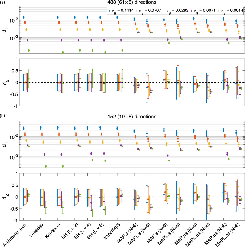
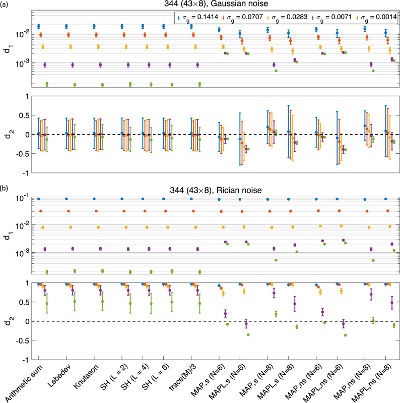
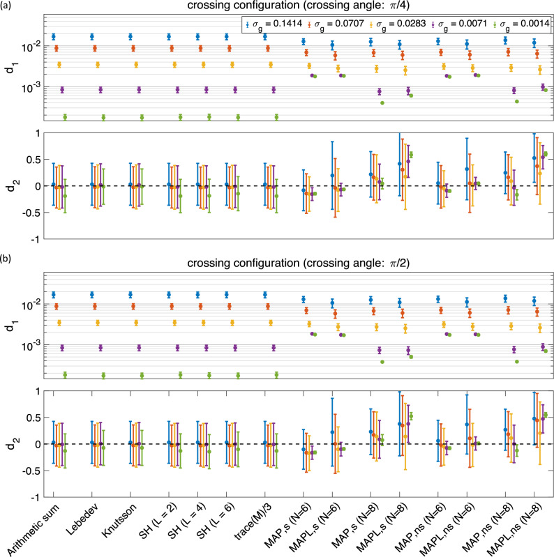
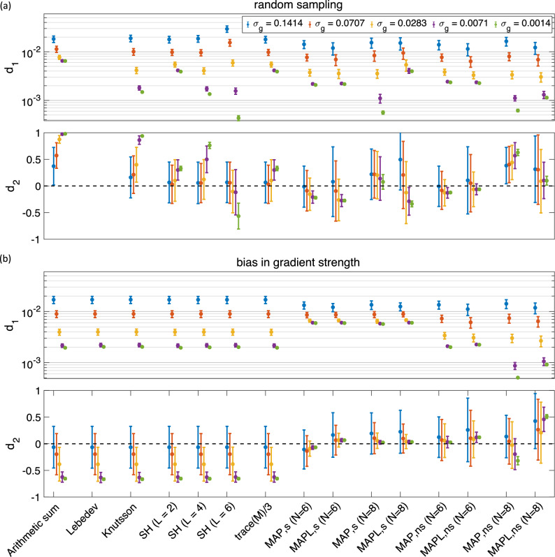
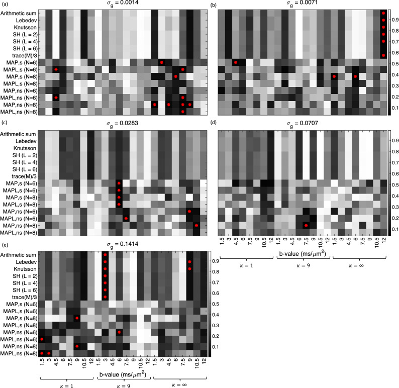
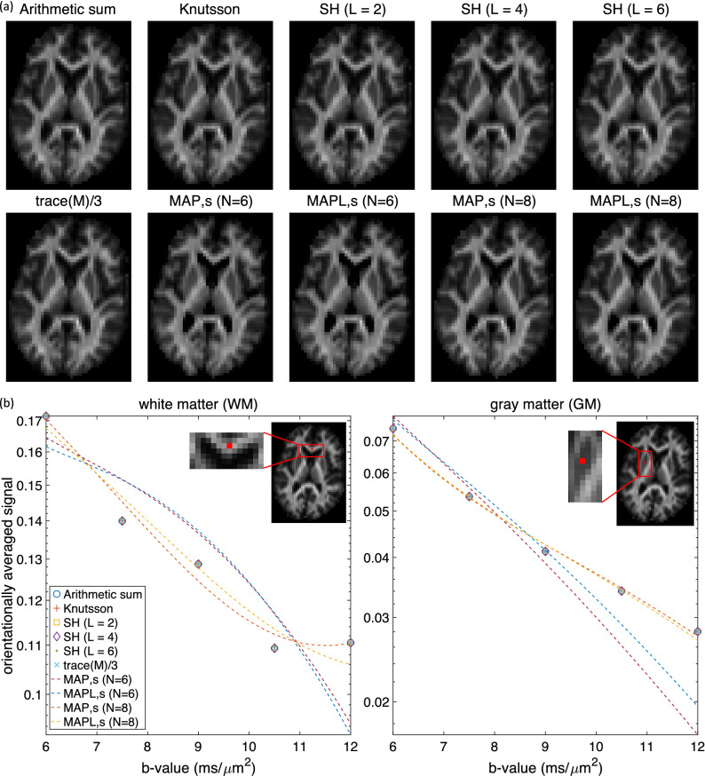
Numerous applications in diffusion MRI involve computing the orientationally-averaged diffusion-weighted signal. Most approaches implicitly assume, for a given b-value, that the gradient sampling vectors are uniformly distributed on a sphere (or 'shell'), computing the orientationally-averaged signal through simple arithmetic averaging. One challenge with this approach is that not all acquisition schemes have gradient sampling vectors distributed over perfect spheres. To ameliorate this challenge, alternative averaging methods include: weighted signal averaging; spherical harmonic representation of the signal in each shell; and using Mean Apparent Propagator MRI (MAP-MRI) to derive a three-dimensional signal representation and estimate its 'isotropic part'. Here, these different methods are simulated and compared under different signal-to-noise (SNR) realizations. With sufficiently dense sampling points (61 orientations per shell), and isotropically-distributed sampling vectors, all averaging methods give comparable results, (MAP-MRI-based estimates give slightly higher accuracy, albeit with slightly elevated bias as b-value increases). As the SNR and number of data points per shell are reduced, MAP-MRI-based approaches give significantly higher accuracy compared with the other methods. We also apply these approaches to in vivo data where the results are broadly consistent with our simulations. A statistical analysis of the simulated data shows that the orientationally-averaged signals at each b-value are largely Gaussian distributed.


Conflict of interest statement

The authors declare no competing interests.

Figures

Figure 1
Figure 1
The mean and std of the d1 and d2 measures (illustrated as, respectively, a dot and an error bar) for different methods and different sampling schemes, in the presence of Gaussian noise (a) 488 (61×8), and (b) 152 (19×8) directions (the y-axis in d1 is scaled logarithmically). Arithmetic sum: simple arithmetic averaging; Lebedev: weighted averaging by; Knutsson: weighted averaging by; SH: Spherical harmonic method for powder averaging by L=2,4,6, shows the order in spherical harmonic representation; trace(M)/3: powder average signal from Eq. (10); MAP: direction-averaged signal using MAP-MRI for Nmax=6 and 8; and MAPL: direction-averaged signal using MAP-MRI with Laplacian regularization. The ‘s’ and ‘ns’ correspond to the shelled and non-shelled point sets, respectively. Different colors (blue, red, yellow, purple, green) show the results in different noise levels (σg=0.1414,0.0707,0.0283,0.0071,0.0014).
Figure 2
Figure 2
The mean and std of the d1 and d2 measures using different methods for 344 samples, both shelled (43×8) and non-shelled point sets in the presence of (a) Gaussian and (b) Rician noise (the y-axis in d1 is scaled logarithmically). The ‘s’ and ‘ns’ correspond to the shelled and non-shelled point sets, respectively. Different colors (blue, red, yellow, purple, green) show the results in different noise levels (σg=0.1414,0.0707,0.0283,0.0071,0.0014).
Figure 3
Figure 3
The estimated d1 and d2 for three different κ values, 344 (43×8) point sets in the presence of five different Gaussian noise levels (the y-axis in d1 is scaled logarithmically). Note that when κ= there is no dispersion; decreasing κ increases the dispersion.
Figure 4
Figure 4
The mean and std of the d1 and d2 measures using different methods for 344 samples in the presence of crossing configuration with (a) π/4 and (b) π/2 radians crossing angle (the y-axis in d1 is scaled logarithmically). The ‘s’ and ‘ns’ correspond to the shelled and non-shelled point sets, respectively. Different colors (blue, red, yellow, purple, green) show the results in different noise levels (σg=0.1414,0.0707,0.0283,0.0071,0.0014).
Figure 5
Figure 5
The mean and std of the d1 and d2 measures for 344 (43×8) samples using different methods for (a) random sampling scheme, and (b) bias in gradient strength (the y-axis in d1 is scaled logarithmically). The ‘s’ and ‘ns’ correspond to the shelled and non-shelled point sets, respectively. Different colors (blue, red, yellow, purple, green) show the results in different noise levels (σg=0.1414,0.0707,0.0283,0.0071,0.0014).
Figure 6
Figure 6
The p-values from the Anderson–Darling test on the orientationally averaged signal obtained from different approaches on 344 (43×8) samples for each b-value and each dispersion value, κ. Panel (a) to (e) show the p-values for different noise levels from σg=0.0014 in (a) to σg=0.1414 in panel (e). The red asterisks illustrate the schemes that the orientationally averaged signal is not Gaussian.
Figure 7
Figure 7
The estimated orientationally averaged signal using different methods for in vivo data on (a) an axial slice for b=6ms/μm2. (b) in a white matter (left plot) and a gray matter (right plot) voxel for b=6,7.5,9,10.5 and 12ms/μm2 in shell-based methods and b=6,6.1,6.2,,12ms/μm2 in MAP-based approaches.

References

    1. Edén M. Computer simulations in solid-state NMR. III. Powder averaging. Concepts Magn. Reson. Part A: Educ. J. 2003;18:24–55. doi: 10.1002/cmr.a.10065. - DOI
    1. Mitra PP, Sen PN. Effects of microgeometry and surface relaxation on NMR pulsed-field-gradient experiments: Simple pore geometries. Phys. Rev. B. 1992;45:143–156. doi: 10.1103/PhysRevB.45.143. - DOI - PubMed
    1. Özarslan E, Basser PJ. Microscopic anisotropy revealed by NMR double pulsed field gradient experiments with arbitrary timing parameters. J. Chem. Phys. 2008;128:04B615. doi: 10.1063/1.2905765. - DOI - PMC - PubMed
    1. Özarslan E. Compartment shape anisotropy (CSA) revealed by double pulsed field gradient MR. J. Magn. Reson. 2009;199:56–67. doi: 10.1016/j.jmr.2009.04.002. - DOI - PMC - PubMed
    1. Jespersen SN, Lundell H, Sønderby CK, Dyrby TB. Orientationally invariant metrics of apparent compartment eccentricity from double pulsed field gradient diffusion experiments. NMR Biomed. 2013;26:1647–1662. doi: 10.1002/nbm.2999. - DOI - PubMed

Publication types