. 2021 Jun 9:11:100119.
doi: 10.1016/j.mtbio.2021.100119. eCollection 2021 Jun.

Topographically guided hierarchical mineralization

Affiliations

Topographically guided hierarchical mineralization

X Deng et al. Mater Today Bio. .

Abstract

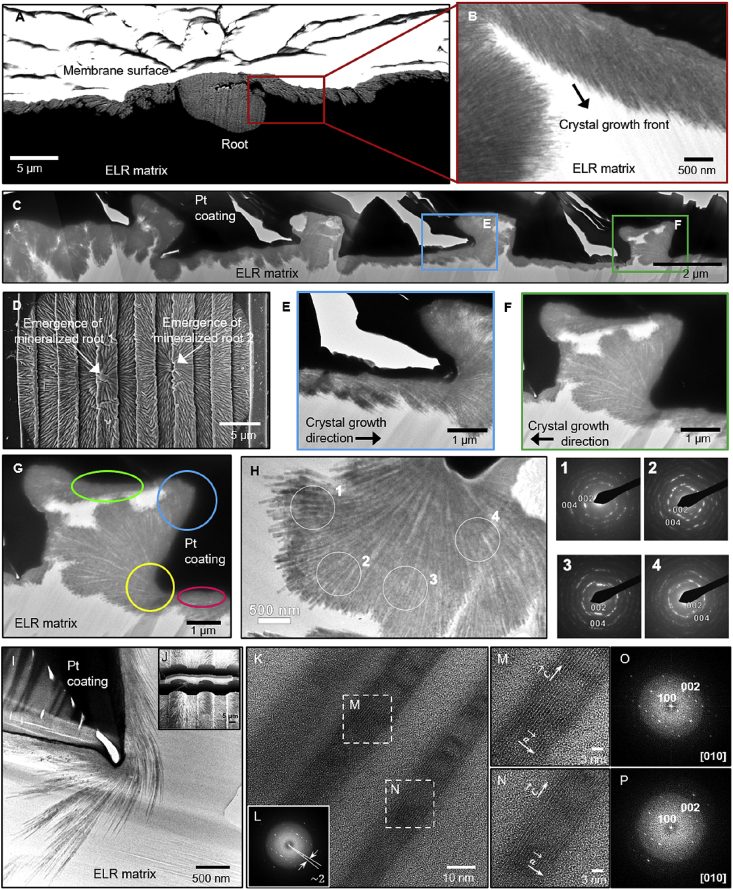
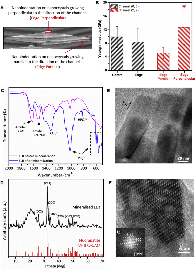
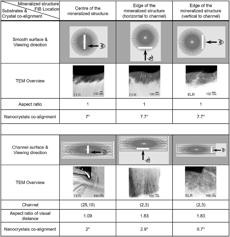
Material platforms based on interaction between organic and inorganic phases offer enormous potential to develop materials that can recreate the structural and functional properties of biological systems. However, the capability of organic-mediated mineralizing strategies to guide mineralization with spatial control remains a major limitation. Here, we report on the integration of a protein-based mineralizing matrix with surface topographies to grow spatially guided mineralized structures. We reveal how well-defined geometrical spaces defined within the organic matrix by the surface topographies can trigger subtle changes in single nanocrystal co-alignment, which are then translated to drastic changes in mineralization at the microscale and macroscale. Furthermore, through systematic modifications of the surface topographies, we demonstrate the possibility of selectively guiding the growth of hierarchically mineralized structures. We foresee that the capacity to direct the anisotropic growth of such structures would have important implications in the design of biomineralizing synthetic materials to repair or regenerate hard tissues.

Keywords: Bone; Crystallization; Dental enamel; Elastin-like recombinamer; Fluorapatite; Hierarchical mineralization; Protein-based biomineralization; Surface topographies.


Conflict of interest statement

The authors declare that they have no known competing financial interests or personal relationships that could have appeared to influence the work reported in this paper.

Figures

Image 1
Graphical abstract
Fig. 1
Fig. 1
Fabrication of topographically patterned surfaces. (A) Schematic illustration of the fabrication of PDMS master and topographically patterned ELR membranes by soft lithography followed by membrane mineralization. (B) 3D representation of microchannel patterns depicting channel width and ridge width and the aspect ratio calculation to characterize the mineralized structures based on the distance covered in the direction parallel (X) and perpendicular (Y) to the channels. (C) Table with the different dimensions of the microchannel surface topographies. (D) SEM images of the patterned ELR membranes before mineralization specifying the respective channel dimensions.
Fig. 2
Fig. 2
Mineralization of ELR membranes. (A) SEM images of a hierarchical mineralized structure grown on a smooth ELR membrane. Mineralized structures grown on the top of ELR membranes with (B) circular-, (C) hexagon-, and (D) star-shaped post topographies. Insets in B and C show non-mineralized circular and hexagonal topographies. Panel E highlighting the different co-alignment between apatite nanocrystals growing on the vertical side of the post (red arrow) and at the junction between the vertical side of the post and the horizontal space between them (white arrow). (F) Graph summarizing the relation between channel dimension and aspect ratio of the mineralized structures grown on patterned ELR membranes. Solid bars correspond to the aspect ratio of visual distance, and striped bars correspond to aspect ratio of growing distance. (G) Cross-section of a microchannel topography highlighting different geometrical spaces within the ELR matrix defined by the topographies including 90°, 180°, and 270° angles. (H) Illustration depicting a mineralized structure with actual and virtual distances traveled by the nanocrystals. (I) SEM images of spherulitic mineralized structures growing on different microchannel dimensions exhibiting different levels of elongation.
Fig. 3
Fig. 3
Characterization of mineralized membranes with zig-zag microchannels.(A, C) SEM images of mineralized structures grown on ELR membranes with zig-zag Channel (2, 2) patterns aligned at 45°, 90°, and 135° corner angles. (B) Graph depicting the relation between the aspect ratio of the mineralized structures and the corner angles of the zig-zag patterns. Solid bars correspond to aspect ratio of visual distance and striped bars correspond to aspect ratio of growing distance. (D) SEM images of the mineralized structures growing along the channel directions and guided by the zig-zag patterns (with 90° and 135° corner angles) over a millimeter length scale. Minor distortions in the channel geometry appeared on zig-zag patterns (highlighted by arrows) in the presence of the mineralized structures, suggesting the presence of stresses being generated by the growing nanocrystals.
Fig. 4
Fig. 4
Bulk characterization. (A) FIB-SEM and (B) TEM image of the cross-section of a smooth ELR membrane showing the nucleation (root) of the mineralized structure and organization of nanocrystals. (C) TEM image of the cross-section of a Channel (2, 3). (D) SEM image of the two adjacent mineralized structures showing the emergence of mineralized roots. Panels E and F show the crystal growth direction within the channel. (G) TEM image of the cross-section of Channel (2, 3), illustrating the organization of nanocrystals growing within the ELR membrane at different angles defined by the surface microchannels (pink and green circle at 180° angle, yellow circle at 270° angle, and blue circle at 90° angle). (H) HRTEM images and SAED patterns displaying the typical crystallographic characteristics of fluorapatite nanocrystals with flat-ended geometry and growing along the c-axis irrespective of the ELR matrix geometry. (I) TEM image of nanocrystals within the ELR matrix of Channel (25, 10). The dark regions in C, G, and I are because of platinum (Pt) coating on the mineralized structures, which is used to prevent sample damage during FIB milling. (J) FIB-SEM image showing cross-sectional lamella preparation via FIB milling. (K, M, and N) HRTEM image of a single fluorapatite nanocrystal showing the growth orientation and crystal lattice. (L, O, and P) Fast Fourier transform (FFT) diffraction pattern of fluorapatite nanocrystals exhibiting a 2° co-alignment angle.
Fig. 5
Fig. 5
Physical characterization of the mineralized membranes.(A) Illustration depicting regions where nanoindentation tests were conducted on the edges of the elliptical-shaped mineralized structures grown on Channel (2, 2) including in the direction parallel and perpendicular to the direction of the channels. (B) Graph summarizing the Young's modulus (E) measurements at different locations on the circular- and elliptical-shaped mineralized structures grown on Channel (0, 0) and Channel (2, 2), respectively. (C) FTIR spectra and (D) XRD pattern confirming the presence of apatite structures and the fluorapatite nature of the crystalline phase, respectively, in the mineralized ELR membrane. (E) TEM image showing a single nanocrystal of 40–50 nm thick flat-ended geometry and (F, G) its corresponding fast Fourier transform (FFT) pattern with typical fluorapatite hexagonal morphology growing along the c-axis. (B) ∗ denotes significant difference between E values for edge parallel vs. edge perpendicular; p < 0.05, estimated using t-test in GraphPad Prism software.
Fig. 6
Fig. 6
Co-alignment degree between adjacent nanocrystals. Table summarizing the relation between aspect ratio and the nanocrystal co-alignment at different locations (i.e. at the center and edges) of the mineralized structures grown on a smooth ELR membrane and on Channel (25, 10) and Channel (2, 3) topographies.

References

    1. Nudelman F., Sommerdijk N.A. Biomineralization as an inspiration for materials chemistry. Angew. Chem. Int. Ed. 2012;51(27):6582–6596. - PubMed
    1. Davis S.A., Dujardin E., Mann S. Biomolecular inorganic materials chemistry. Curr. Opin. Solid State Mater. Sci. 2003;7(4–5):273–281.
    1. Xu H., Smith D., Jahanmir S., Romberg E., Kelly J., Thompson V., Rekow E. Indentation damage and mechanical properties of human enamel and dentin. J. Dent. Res. 1998;77(3):472–480. - PubMed
    1. Boyde A. 1989. Enamel, Teeth; pp. 309–473. Springer.
    1. Beniash E., Stifler C.A., Sun C.-Y., Jung G.S., Qin Z., Buehler M.J., Gilbert P.U.P.A. The hidden structure of human enamel. Nat. Commun. 2019;10(1):4383. - PMC - PubMed