Review
. 2021 Jul 12;26(14):4236.
doi: 10.3390/molecules26144236.

Nanocarbon-Iridium Oxide Nanostructured Hybrids as Large Charge Capacity Electrostimulation Electrodes for Neural Repair

Affiliations
Review

Nanocarbon-Iridium Oxide Nanostructured Hybrids as Large Charge Capacity Electrostimulation Electrodes for Neural Repair

Nieves Casañ-Pastor. Molecules. .

Abstract

Nanostructuring nanocarbons with IrOx yields to material coatings with large charge capacities for neural electrostimulation, and large reproducibility in time, that carbons do not exhibit. This work shows the contributions of carbon and the different nanostructures present, as well as the impact of functionalizing graphene with oxygen and nitrogen, and the effects of including conducting polymers within the hybrid materials. Different mammalian neural growth models differentiate the roles of the substrate material in absence and in presence of applied electric fields and address optimal electrodes for the future clinical applications.

Keywords: charge capacity; electrostimulation; iridium oxide; nanocarbons; repair.


Conflict of interest statement

The authors declare there is no conflict of interests.

Figures

Figure 1
Figure 1
(AD) Time evolution of TEM images at about 10 min intervals, showing TEM images of dry drops of Iridium oxo solutions obtained from hydrolysis of IrCl3, evolve under the electron microscope (120 KV Jeol). Last two images, (E,F) Diffraction rings obtained at this low resolution match those of quasiamorphous KxIrO2 and later metallic Ir. Thermal evolution has also been observed before in Ar atmosphere (in O2 yielding IrO2 rutile [21]) Images show two different time intervals. Global time in the order of minutes. (Original results).
Figure 2
Figure 2
Top: (A) Simultaneous cyclic voltammetry and ECQM mass changes during dynamic Electrodeposition of IrOx involving mass deposition and K+ intercalation/deintercalation, (B) SEM lateral images of resulting coatings on Pt (12 nm) glass slides, (C) Macroscopic images of IrOx deposited on Pt (12 nm)-Ti (5 nm)-glass substrates. Bottom (D) Typical electrodeposition Cyclic voltammetry of IrOx-Nanocarbon hybrids (this case IrOx-NGO) (E) macroscopic images showing that the first layers are mostly IrOx and (F) SEM lateral images of the coatings. From ref. [24,29] Published with permission of Elsevier.
Figure 3
Figure 3
(A) Exfoliated graphite yielding pristine graphene and (B,C) adhesion of Ir oxoparticles adhered to electrochemically exfoliated graphene nanoparticles, eG ((A,B) HRTEM, (C) SEM). (Note that Iridium species evolve under the microscope).
Figure 4
Figure 4
SEM images of IrOx-CNT (top AC) and IrOx-CNT-PEDOT hybrids (bottom DF) [18,27]. With permission from Elsevier.
Figure 5
Figure 5
(AD) SEM images for IrOx-GO hybrid at various scales showing typical cracks and the millfeuille nanostructure [28]. Yellow big square shows a magnified vision of the zone at small square. With permission from Elsevier.
Figure 6
Figure 6
(A) SEM images of IrOx-eG hybrid showing the millfeuille nanostructure. (inset: macro scale showing the large homogeneity of the coating). (B) Crack developed under the SEM electron beam with millfeuille ordering. (Inset showing secondary electrons image, where carbon is not seen vs iridium) [24]. With permission from Elsevier.
Figure 7
Figure 7
SEM images of IrOx-NGO hybrid coatings for one of the IrOx—NGO hybrid (NGO treated at 100 °C (A,D), 220 °C (B,E) and 300 °C (C,F) [29]. With permission from Elsevier.
Figure 8
Figure 8
(A) Cyclic voltammetries in biologically emulating sodium phosphate buffer of representative nanostructured IrOx–graphene hybrids during electric field application in electrostimulation processes and (B) associated charge storage capacity changes during 1000 cycles. (C) Graphite hybrid, not shown sees the CSC decrease after a few cycles, to the IrOx values. (D) Impedance comparison for several materials [34]. With permission from Elsevier.
Figure 9
Figure 9
CV showing the significant decrease in current when PEDOT is incorporated to the IrOx-CNT hybrid. (IrOx-CNT compared with IrOx-CNT-PEDOT and with individual components). The lowest currents always correspond to the composites or hybrids containing PEDOT [18]. With permission from Elsevier.
Figure 10
Figure 10
Neuronal survival and functionality on IrOx-eG. Representative fluorescent microphotographs of neurons growing on: (A) Borosilicate glass, (B) IrOx, (C) IrOx-eG and (D) Platinum, stained against Tau (red) and NeuN (green) showing dendrites and living cell nucleii. Scale bar = 100 µm [24]. With permission from Elsevier.
Figure 11
Figure 11
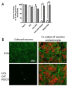
Astrocyte influence on neuronal survival on IrOx.nanocarbon nanostructured materials containing conducting polymer PEDOT with respect to IrOx. (A) Dissociated neural cells were (seeded at 115,000 cells × cm−2 on different materials coated with poly-L-lysine (white bars) or with a monolayer of confluent astrocytes (cross bars) and grown for 5 DIV. (B) Representative fluorescent photomicrographs of primary cultures of enriched neurons and of neuron-astrocyte co-culture growing on IrOx and IrOx-CNTPEDOT. Cells were processed for tau (green) and GFAP (red) immunocytochemistry to label neurons and astrocytes, respectively. Scale bar = 100 μm [18]. *** p < 0.001 vs. neurons grown on poly-L-lysine coated materials. With permission from Elsevier.
Figure 12
Figure 12
(A) Quantification of neural cell growth in absence and presence of EF with Q delivered below (80% of the total CSC) and above CSC (based on Tau imunostaining of scratched cortical neuron cultures showing spontaneous regeneration of surface covered by new neurites after scratching the neuronal monolayer at 5 DIV in each case) [34]. (B) Representative images of cell growth with no field and using (80% and 200% of the CSC value for the charge delivery). (B) Neurite and nuclei images for comparison (Cells were processed for Tau inmunocitochemistry and Bis-benzimide staining of the nuclei). With permission from Elsevier.
Figure 13
Figure 13
Spontaneous regeneration of an in vitro “wound like” scratch in neural cell cultures over IrOx-eG hybrid. (A) Tau imunostaining of scratched cortical neuron cultures showing spontaneous regeneration of surface covered by new neurites after scratching the neuronal monolayer at 5 DIV. (B1) Neurite and (B2) nuclei images for comparison (Cells were processed for Tau inmunocitochemistry and Bis-benzimide staining of the nuclei). (C) Quantitative integration of the area covered by new neurites at different days after scratch. Results are mean ± sem (n = 5). * p < 0.05; ** p < 0.01, *** p < 0.001 vs. t = 0 after significant one-way ANOVA. Electric field application would be carried out in a zone where a more drastic change is seen for growth (d2, marked in the red arrow) [34].
Figure 14
Figure 14
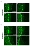
Scratch model repair under the application of an electric field using IrOx-graphene as substrate, (A) cin cathode and (B) anode areas. The firs image in each set corresponds to the reference spontaneous scratch growth using polypyrrole surface on PEDOT with lysine counterions. (Note that cells are near polypyrrole and not PEDOT in the polymer bilayer). Scale bars are equal for all images. [22] B-lys is a PEDOT-Polypyrrole bilayer with lysine counterion, IrOx-eG is the hybrid described in this work. With permission from Elsevier.
Figure 15
Figure 15
(A) Quantification of scratch repair (as area reoccupied by neurites) for various pairs of electrode materials, using symmetrical cells (equal electrodes), or reducing first the electrode that will act as anode, as compared with spontaneous repair [34]. Results are mean ± sem. * p < 0.05 and ** p < 0.01 after significant one-way ANOVA (p < 0.05; F3,15 = 3.486) and post-comparison tests. (B) Quantification of scratch repair (as area occupied), as compared with the use of Pt electrodes. With permission from Elsevier.

References

    1. Frackowiak E., Beguin F. Carbon materials for the electrochemical storage of energy in capacitors. Carbon. 2001;39:937–950. doi: 10.1016/S0008-6223(00)00183-4. - DOI
    1. Lang A., Hirata A., Fujita T., Chen M. Nanoporous metal/oxide hybrid electrodes for electrochemical supercapacitors. Nat. Nanotechnol. 2011;6:232–236. doi: 10.1038/nnano.2011.13. - DOI - PubMed
    1. Deng X., Li J., Ma L., Sha J., Zhao N. Three-dimensional porous carbon materials and their composites as electrodes for electrochemical energy storage systems. Mater. Chem. Front. 2019;3:2221–2245. doi: 10.1039/C9QM00425D. - DOI
    1. Lyu L., Seong K.D., Ko D., Choi J., Lee C., Hwang T., Cho Y., Jin X., Zhang W., Pang H., et al. Recent developent of biomass-derived carbons and composites as electrode materials for supercapacitors. Mater. Chem. Front. 2019;3:2543–2570. doi: 10.1039/C9QM00348G. - DOI
    1. Zhang G., Han Y., Shao C., Chen N., Sun G., Jin X., Gao J., Ji B., Yang H., Qu L. Processing and manufacturing of graphene-based microsupercapacitors. Mater. Chem. Front. 2018;2:1750–1764. doi: 10.1039/C8QM00270C. - DOI

LinkOut - more resources