Review
. 2021 Jul 9;14(14):3841.
doi: 10.3390/ma14143841.

Peening Techniques for Surface Modification: Processes, Properties, and Applications

Affiliations
Review

Peening Techniques for Surface Modification: Processes, Properties, and Applications

Merbin John et al. Materials (Basel). .

Abstract

Surface modification methods have been applied to metals and alloys to change the surface integrity, obtain superior mechanical properties, and improve service life irrespective of the field of application. In this review paper, current state-of-the-art of peening techniques are demonstrated. More specifically, classical and advanced shot peening (SP), ultrasonic impact peening (UIP), and laser shock peening (LSP) have been discussed. The effect of these techniques on mechanical properties, such as hardness, wear resistance, fatigue life, surface roughness, and corrosion resistance of various metals and alloys, are discussed. This study also reports the comparisons, advantages, challenges, and potential applications of these processes.

Keywords: fatigue life; laser shock peening; microstructure; severe plastic deformation; shot peening; ultrasonic impact peening.


Conflict of interest statement

The authors declare no conflict of interest. The funders had no role in the design of the study; in the collection, analyses, or interpretation of data; in the writing of the manuscript, or in the decision to publish the results.

Figures

Figure 1
Figure 1
Schematic illustration of different peening techniques and the corresponding plastically deformed top surface of the target material: (a) SP; (b) UIP; (c) LSP. Reproduced with permission from [44]. Copyright Elsevier, 2021.
Figure 2
Figure 2
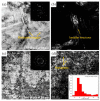
TEM bright field (BF) and the corresponding dark filed (DF) image from the topmost surface of treated Hastelloy X alloy: (a,b) SP; (c,d) SSP sample. Inset in Figure 2d is the statistical distribution of the grain size. Reproduced with permission from [64]. Copyright Elsevier, 2021.
Figure 3
Figure 3
The illustration of grain refinement mechanism of Mg-8Gd-3Y alloy during SSP. Reproduced with permission from [70]. Copyright Elsevier, 2020.
Figure 4
Figure 4
SEM of cast iron surfaces developed by (a) SP; (b) SSP and (c) RSSP. Reproduced with permission from [71]. Copyright Elsevier, 2014.
Figure 5
Figure 5
Ultrasonic peening equipment. Reproduced with permission from [80]. Copyright Elsevier, 2015.
Figure 6
Figure 6
TEM showing (a) trapezoidal Al2Cu particle as emission source of dislocations (b) DC and DT in the aluminum matrix. Reproduced with permission from [38]. Copyright Elsevier, 2002.
Figure 7
Figure 7
SEM of SS 304 sheets (a) microcracks in weld toe; (b) after UIP treatment closure of microcracks and modified weld toe curvature. Reproduced with permission from [39]. Copyright Elsevier, 2012.
Figure 8
Figure 8
Comparison of the data at the same depth for (a) the variation of magnetization with martensite ratio; and (b) variation of the coercivity with grain size. Reproduced with permission from [83]. Copyright Elsevier, 2020.
Figure 9
Figure 9
SEM of weld bead of CMT welded 6062 aluminum alloy (a) without UIP; (b) with UIP. Reproduced with permission from [85]. Copyright Elsevier, 2018.
Figure 10
Figure 10
Polarization curves for specimens with different impact intensities. Reproduced with permission from [92]. Copyright Elsevier, 2021.
Figure 11
Figure 11
Cross-sectional morphologies of laser cladded AlCoCrCuFeNi HEA coatings: (a) without UIT; (b) with UIT. Reproduced with permission from [94]. Copyright Elsevier, 2021.
Figure 12
Figure 12
LSP on ANSI 304 SS and variation of (a) nano hardness and elastic moduli (b) residual stress with and without LSP. Reproduced with permission from [27]. Copyright Elsevier, 2011.
Figure 13
Figure 13
Optical micrographs of cross-section of 316L steel subjected to (a) SP; (b) LSP. Reproduced with permission from [115]. Copyright Elsevier, 2000.
Figure 14
Figure 14
TEM on (a) LSP treated; (b) untreated specimen Ti6Al4V alloy. Reproduced with permission from [116]. Copyright Elsevier, 1999.
Figure 15
Figure 15
Surface profile comparisons (a) BM; (b) SP and (c) LSP treated specimen. Reproduced with permission from [117]. Copyright Elsevier, 2012.
Figure 16
Figure 16
Typical TEM images of the LSP’ed SLM specimen. (a) Refined acicular martensite and MTs (b) dislocations and refined acicular martensite. Reproduced with permission from [120]. Copyright Elsevier, 2021.
Figure 17
Figure 17
The experimental system of nanoparticle implantation induced by LSP. Reproduced with permission from [123]. Copyright Elsevier, 2021.
Figure 18
Figure 18
Comparison of WLSP and LSP on AISI 4140 steel (a) stress relaxation at 300 °C; (b) stress relaxation after cyclic loading. Reproduced with permission from [131]. Copyright Elsevier, 2011.
Figure 19
Figure 19
Integrated SLM with LSP (a) Process diagram and (b) laser scanning strategy. Reproduced with permission from [136]. Copyright Elsevier, 2020.
Figure 20
Figure 20
(a) Surface hardness and (b) roughness measurements in fs-LSP processed SS 304 under different conditions. Reproduced with permission from [140]. Copyright Elsevier, 2021.
Figure 21
Figure 21
A schematic illustration of indirect-LSSP process. Reproduced with permission from [146]. Copyright Elsevier, 2018.
Figure 22
Figure 22
OM showing the microstructure of direct-LSSP-patterned AZ31B with laser intensities of: (a) 0; (b) 1.18; (c) 1.47; (d) 1.70; (e) 1.92; and (f) 2.12 GW/cm2. Reproduced with permission from [147]. Copyright Elsevier, 2020.
Figure 23
Figure 23
TEM images of dislocations in α-SiC ceramics generated by LSP: (a) weak-beam dark- field and (b) bright-field images of dislocations underneath the surface. Reproduced with permission from [149]. Copyright Elsevier, 2019.

References

    1. Azhari A., Sulaiman S., Rao A.K.P. A review on the application of peening processes for surface treatment. IOP Conf. Ser. Mater. Sci. Eng. 2016;114 doi: 10.1088/1757-899X/114/1/012002. - DOI
    1. Nagarajan B., Kumar D., Fan Z., Castagne S. Effect of deep cold rolling on mechanical properties and microstructure of nickel-based superalloys. Mater. Sci. Eng. A. 2018;728:196–207. doi: 10.1016/j.msea.2018.05.005. - DOI
    1. Tao N.R., Wang Z.B., Tong W.P., Sui M.L., Lu J., Lu K. An investigation of surface nanocrystallization mechanism in Fe induced by surface mechanical attrition treatment. Acta Mater. 2002;50:4603–4616. doi: 10.1016/S1359-6454(02)00310-5. - DOI
    1. Kovacı H., Yetim A.F., Baran Ö., Çelik A. Tribological behavior of DLC films and duplex ceramic coatings under different sliding conditions. Ceram. Int. 2018;44:7151–7158. doi: 10.1016/j.ceramint.2018.01.158. - DOI
    1. Lowe T.C., Valiev R.Z. The use of severe plastic deformation techniques in grain refinement. JOM. 2004;56:64–68. doi: 10.1007/s11837-004-0295-z. - DOI

LinkOut - more resources