Review
. 2021 Jul 12;13(14):2276.
doi: 10.3390/polym13142276.

Mechanical Energy Sensing and Harvesting in Micromachined Polymer-Based Piezoelectric Transducers for Fully Implanted Hearing Systems: A Review

Affiliations
Review

Mechanical Energy Sensing and Harvesting in Micromachined Polymer-Based Piezoelectric Transducers for Fully Implanted Hearing Systems: A Review

Rhonira Latif et al. Polymers (Basel). .

Abstract

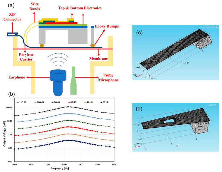
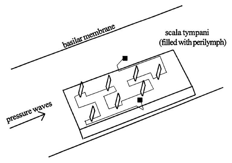
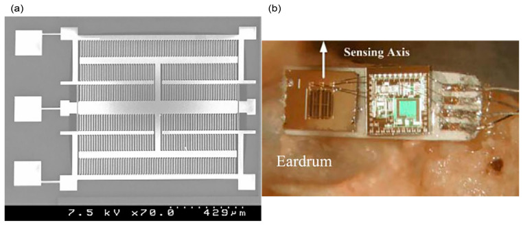
The paper presents a comprehensive review of mechanical energy harvesters and microphone sensors for totally implanted hearing systems. The studies on hearing mechanisms, hearing losses and hearing solutions are first introduced to bring to light the necessity of creating and integrating the in vivo energy harvester and implantable microphone into a single chip. The in vivo energy harvester can continuously harness energy from the biomechanical motion of the internal organs. The implantable microphone executes mechanoelectrical transduction, and an array of such structures can filter sound frequency directly without an analogue-to-digital converter. The revision of the available transduction mechanisms, device configuration structures and piezoelectric material characteristics reveals the advantage of adopting the polymer-based piezoelectric transducers. A dual function of sensing the sound signal and simultaneously harvesting vibration energy to power up its system can be attained from a single transducer. Advanced process technology incorporates polymers into piezoelectric materials, initiating the invention of a self-powered and flexible transducer that is compatible with the human body, magnetic resonance imaging system (MRI) and the standard complementary metal-oxide-semiconductor (CMOS) processes. The polymer-based piezoelectric is a promising material that satisfies many of the requirements for obtaining high performance implantable microphones and in vivo piezoelectric energy harvesters.

Keywords: MEMS sensor; energy harvester; hearing aids; implantable microphone; piezoelectric-polymers.


Conflict of interest statement

The authors declare no conflict of interest. The funders had no role in the design of the study; in the collection, analyses, or interpretation of data; in the writing of the manuscript, or in the decision to publish the results.

Figures

Figure 1
Figure 1
The schematic of (a) cochlear implant (CI) [1], (b) middle ear implant (MEI), photo credit: MED-EL [3], (c) hearing aid and (d) bone-anchored hearing aid (BAHA), photo credit: MED-EL [9].
Figure 2
Figure 2
(a) Electric power generating system for implanted medical devices is proposed by positioning a human body in a rotating magnetic field. © 1999 IEEE. Reprinted, with permission, from [31]. (b) Optical image of the flexible piezoelectric transducers array for ultrasonic energy harvesting. Reprinted from [32], Copyright (2019), with permission from Elsevier. (c) A schematic diagram of a nanowire piezoelectric nanogenerator driven by an ultrasonic wave [33].
Figure 3
Figure 3
(a) Side view of a MEMS acoustic energy harvester chip attached on a carrier with epoxy bumps. (b) The schematic view of the piezoelectric transducer on the ear drum mimicking membrane. (c) Measured frequency sweep results of the prototype chip. Modified from [46].
Figure 4
Figure 4
(a) Cantilever beam with top proof mass and (b) the equivalent spring-mass-damper system. © 2013 IEEE. Reprinted, with permission, from [47]. (c) The cross section of a T-shape cantilever beam with top proof mass and (d) its first modal shape. © 2019 IEEE. Reprinted, with permission, from [48].
Figure 5
Figure 5
(a) Top view and (b) cross sectional view of the PZT diaphragm energy harvester. (c) Possible charge distribution at first mode and (d) the conceptual schematic of peripheral and central energy harvesting [49]. Copyright (2011) The Japan Society of Applied Physics.
Figure 6
Figure 6
(a) The acoustic characterisation setup and (b) the measured acoustic results of a PZT energy harvester at sound pressure level from 60 dB to 100 dB SPL. Reprinted from [50], Copyright (2018), with permission from Elsevier. The meshed (c) rectangular and (d) tapered perforated ZnO cantilever structure with proof mass. The tapered perforated structure has the same area as the rectangular cantilever and the narrower side is fixed while the broader side is free to vibrate. © 2017 IEEE. Reprinted, with permission, from [51].
Figure 7
Figure 7
The schematic of vertical PVDF cantilevers device positioned in the scala tympani of a cochlea [58]. Reprinted by permission from Springer Nature Customer Service Centre GmbH: Springer Nature MRS ONLINE PROCEEDINGS LIBRARY Considerations in the Development of a Piezoelectric Transducer Cochlear Implant, N. Mukherjee et al., COPYRIGHT (2011).
Figure 8
Figure 8
(a) The schematic diagram of PVDF membrane (yellow) with 24 aluminium top electrodes fabricated on a trapezoidal slit of a stainless plate. (b) The schematic drawing of the implantable P(VDF-TrFE) membrane and (c) the integrated optical image of the implanted P(VDF-TrFE) membrane in the basal turn of the cochlea [60].
Figure 9
Figure 9
(a) The morphology of electrospun BTNP/PVDF fibres at 20/80 weight composition, collected on a rotating disk at high tangential velocity of 22 ms−1. (b) Dispersion of BTNPs inside the electrospun PVDF fibres where beads are induced by the presence of BTNP aggregation [68] Copyright (2017), with permission from Elsevier.
Figure 10
Figure 10
(a) Gold IDEs patterned on the flexible PZT film and the simulated potential distribution in PZT film between the adjacent electrodes. (b) The principle operation of piezoelectricity generation in iPANS device (i) before and (ii) after bending deformation. (c) The attachment of an iPANS device on a 1 cm curvature radius of glass rod. (d) The conceptual schematic of flexible iPANS device insertion under BM in a mammalian cochlea. The upward bending at 600 nm due to sound wave vibration generates 3 V of piezoelectric potential [69].
Figure 11
Figure 11
Twelve groups of 10 MEHs clamped on a bending stage in (a) flat and (b) bent config-uration. (c) The PZT/PI MEHs device is connected and integrated with a rectifier and rechargea-ble microbattery. (d,e) The integrated MEHs is attached onto the right ventricle of bovine heart during expansion and relaxation. (f) The illustration of a multilayer stack of five PZT/PI MEHs sheets connected in series and the equivalent schematic circuit [70].
Figure 12
Figure 12
(a) Schematic illustration of the fabrication process and biomedical application of the flexible PMN-PT/PET piezoelectric energy harvester. (b)The piezoelectrical generation of the flexible PMN-PT/PET thin film (i) before and (ii) after bending. (c) The simulated piezoelectric potential distribution in PMN-PT thin film under tensile strain of 0.36% [71].
Figure 13
Figure 13
(a) Composite with 3-1 connectivity in which rods of piezoelectric are embedded in a three-dimensionally continuous polymer. PZT rods can be poled along the length and thus the direction of the PZT/epoxy composite is along the direction of the rods alignment [73]. (b) The measured hydrostatic piezoelectric constant of a composite PZT/foamed PU as a function of porosity in PU matrix [74].
Figure 14
Figure 14
The schematic illustration of an uncoiled basilar membrane demonstrating the tonotopic organisation behaviour along the membrane length [77]. Reprinted by permission from Springer Nature Customer Service Centre GmbH: Springer Nature MICROSYSTEM TECHNOLOGIES MEMS design and modelling based on resonant gate transistor for cochlear biomimetical application, R. Latif et al., COPYRIGHT (2016).
Figure 15
Figure 15
(a) 4-channel multiresonant microphone made of four free-standing cantilevers with different lengths. There is a 20 µm air gap between the cantilevers and the receiving light pipes. (b) The measured frequency response from the cantilevers at 70 dB SPL. (c) The tonotopic mapping characteristics of a human cochlea demonstrating the frequency point as a function of distance from apex of cochlea. (d) The corresponding length of a cantilever that can give the required resonant frequency fc at the frequency points [75]. Reprinted by permission from S. Karger AG, Basel.
Figure 16
Figure 16
The proposed fibre-optic vibrometer system for middle ear implant. © 2002 IEEE. Reprinted, with permission, from [78].
Figure 17
Figure 17
(a) The structural design of bionic acoustic triboelectric-based sensor. Two rectangular acrylic plates with trapezoidal cavity are used as the frames to support the PTFE membranes. The silver electrodes are numbered from electrode #1 to #9. (b) The simulated vibration characteristics of a trapezoidal PTFE membrane at 300 Hz, 1000 Hz and 2000 Hz of frequency input [76].
Figure 18
Figure 18
(a) (i) The schematic drawing and (ii) the optical image of eight Al/Kapton/Au beams on substrate. (b) The experimental setup for animal testing using the triboelectric acoustic sensor including the signal processor and the custom-made intra-cochlear electrode array [79].
Figure 19
Figure 19
The neodymium iron boron magnet (2) at malleus is moved by the tympanic membrane (1) and interacts with the electromagnetic coil of 1900 turns (3). The supporting titanium shaft (4) is screwed to the temporal bone (5). The generated electrical signals from the coil are sent to the CI multichannel electrode array (15) in the cochlea. Reprinted from [80], Copyright (2001), with permission from Elsevier.
Figure 20
Figure 20
(a) The position of the implantable electrostatic-based microphone. (b) The block diagram of the microphone [81].
Figure 21
Figure 21
(a) The proposed fully implantable microphone at umbo in the middle ear. (b) The 2D layout of the accelerometer with differential capacitances. The capacitive sensed-fingers are connected to the proof mass through a system of microlevers [82]. Reprinted by permission from Springer Nature Customer Service Centre GmbH: Springer Nature MICROSYSTEM TECHNOLOGIES Numerical simulation and modelling of a novel MEMS capacitive accelerometer based microphone for fully implantable hearing aid, A. Dwivedi et al., COPYRIGHT (2019).
Figure 22
Figure 22
(a) The micrograph image of the fabricated capacitive accelerometer-based microphone. (b) The accelerometer is interfaced with the low-noise differential capacitance-to-voltage conversion circuitry and then implanted onto umbo. © 2012 IEEE. Reprinted, with permission, from [83].
Figure 23
Figure 23
(a) The circular membranes of different diameters are fabricated using random and aligned P(VDF-TrFE) nanofibers, mimicking the function of a basilar membrane. The fibrous microphone membrane is based on electrospun piezoelectric polymer nanofibres with (b) random P(VDF-TrFE) fibres and (c) aligned P(VDF-TrFE) fibres [84]. Further permissions related to the material excerpted should be directed to the ACS.
Figure 24
Figure 24
(a) The optical image of the fabricated Mo/AlN/Au beam array [86]. © IOP Publishing. Reproduced with permission. All rights reserved. (b) The schematic view of the experimental setup using Mo/AlN/Au cantilever array that generates piezoelectric voltage to the signal processor and intra-cochlear electrode array. The stimulating electrical signals onto the cochlea elicit eABR response from a deafened guinea pig [87].
Figure 25
Figure 25
(a) Top view of the trampoline (left), annular (middle) and hexagonal beams with square seismic mass (right) piezoelectric accelerometers. (b) The geometric parameters, boundary conditions and body force imposed in the finite element model, represented in a sectional view of the annular accelerometer [89].
Figure 26
Figure 26
(a) The proposed piezoelectric cantilevers placement on the tympanic membrane (b) the bulk piezoelectric cantilever on the eardrum membrane model. © 2013 IEEE. Reprinted, with permission, from [90].
Figure 27
Figure 27
(a) SixNy membrane of dimension 0.5 mm × 0.5 mm with four AlN/Au piezoelectric elements. (b) The cross-section schematic of device showing AlN and gold electrodes operating in mode 33. Reprinted from [43], Copyright (2015), with permission from Elsevier.
Figure 28
Figure 28
(a) Scanning electron microscopy image and (b) top view optical image of a single paddle-shaped cantilever microphone. © 2013 IEEE. Reprinted, with permission, from [91].

Similar articles

Cited by

References

    1. Kral A. Auditory critical periods: A review from system’s perspective. Neuroscience. 2013;247:117–133. doi: 10.1016/j.neuroscience.2013.05.021. - DOI - PubMed
    1. Zeng F.-G., Rebscher S., Harrison W.V., Sun X., Feng H. Cochlear Implants: System Design, Integration, and Evaluation. IEEE Rev. Biomed. Eng. 2008;1:115–142. doi: 10.1109/RBME.2008.2008250. - DOI - PMC - PubMed
    1. Middle Ear Implant. [(accessed on 29 June 2021)]; Available online: https://www.medel.com/hearing-solutions/vibrant-soundbridge.
    1. Pegan A., Ries M., Ajduk J., Bedeković V., Ivkić M., Trotić R. Active Middle Ear Vibrant Soundbridge Sound Implant. Acta Clin. Croat. 2019;58:348–353. doi: 10.20471/acc.2019.58.02.20. - DOI - PMC - PubMed
    1. Shin D.H., Cho J.H. Piezoelectric Actuator with Frequency Characteristics for a Middle-Ear Implant. Sensors. 2018;18:1694. doi: 10.3390/s18061694. - DOI - PMC - PubMed

LinkOut - more resources