. 2021 Jul;82(Suppl 3):e248-e258.
doi: 10.1055/s-0039-3399590. Epub 2019 Nov 28.

Foundations of Advanced Neuroanatomy: Technical Guidelines for Specimen Preparation, Dissection, and 3D-Photodocumentation in a Surgical Anatomy Laboratory

Affiliations

Foundations of Advanced Neuroanatomy: Technical Guidelines for Specimen Preparation, Dissection, and 3D-Photodocumentation in a Surgical Anatomy Laboratory

Luciano César Pc Leonel et al. J Neurol Surg B Skull Base. 2021 Jul.

Abstract

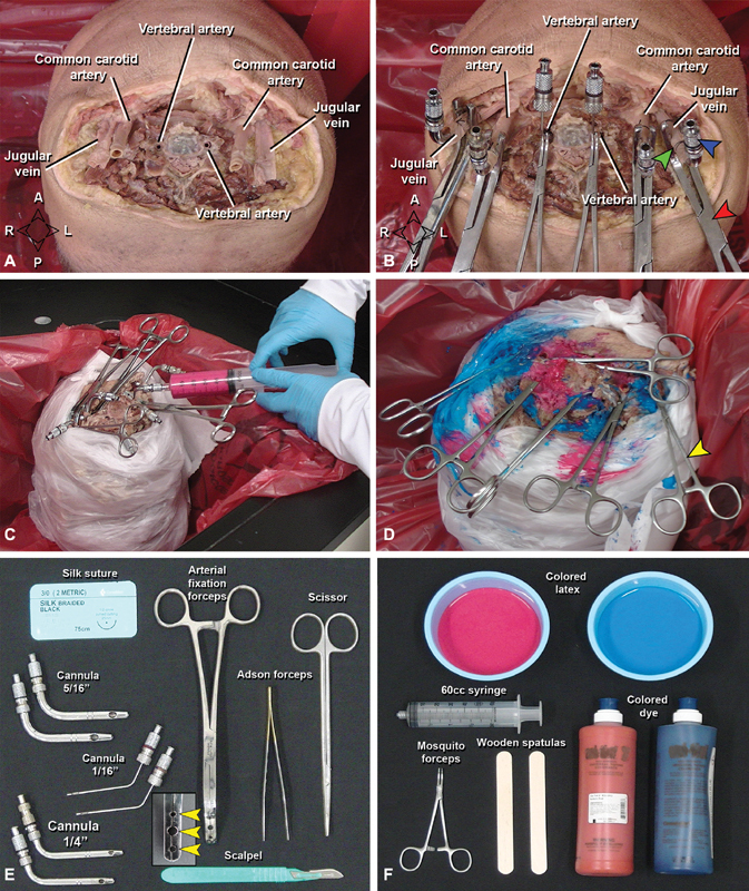
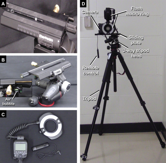
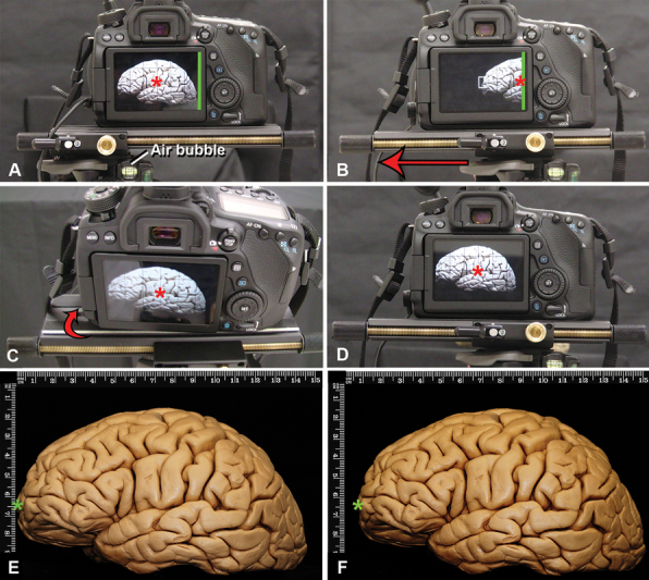
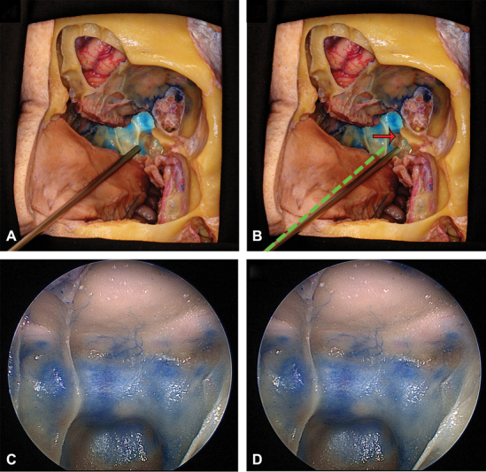
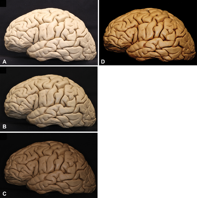
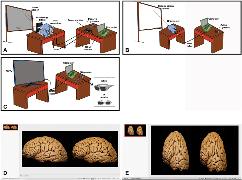
Objective This study was aimed to provide a key update to the seminal works of Prof. Albert L. Rhoton Jr., MD, with particular attention to previously unpublished insights from the oral tradition of his fellows, recent technological advances including endoscopy, and high-dynamic range (HDR) photodocumentation, and, local improvements in technique, we have developed to optimize efficient neuroanatomic study. Methods Two formaldehyde-fixed cadaveric heads were injected with colored latex to demonstrate step-by-step specimen preparation for microscopic or endoscopic dissection. One formaldehyde-fixed brain was utilized to demonstrate optimal three-dimensional (3D) photodocumentation techniques. Results Key steps of specimen preparation include vessel cannulation and securing, serial tap water flushing, specimen drainage, vessel injection with optimized and color-augmented latex material, and storage in 70% ethanol. Optimizations for photodocumentation included the incorporation of dry black drop cloth and covering materials, an imaging-oriented approach to specimen positioning and illumination, and single-camera stereoscopic capture techniques, emphasizing the three-exposure-times-per-eye approach to generating images for HDR postprocessing. Recommended tools, materials, and technical nuances were emphasized throughout. Relative advantages and limitations of major 3D projection systems were comparatively assessed, with sensitivity to audience size and purpose specific recommendations. Conclusion We describe the first consolidated step-by-step approach to advanced neuroanatomy, including specimen preparation, dissection, and 3D photodocumentation, supplemented by previously unpublished insights from the Rhoton fellowship experience and lessons learned in our laboratories in the past years such that Prof. Rhoton's model can be realized, reproduced, and expanded upon in surgical neuroanatomy laboratories worldwide.

Keywords: anatomy; dissection; education; endoscopy; imaging; neuroanatomy; skull base; three-dimensional photography.


Conflict of interest statement

Conflict of Interest L.P.C. reports grants from Mayo Foundation, during the conduct of the study. M.P.C. reports grants from NREF, grants from Medtronic, grants from Storz, grants from CAPES, grants from Mayo Foundation, during the conduct of the study. L.C.P.C.L. reports grants from CAPES, during the conduct of the study.A.P. reports grants from Mayo Clinic, during the conduct of the study. M.J.L. reports grants from Mayo Foundation, during the conduct of the study.

Figures

Fig. 1
Fig. 1
Cannulation, flushing and latex injection of the specimen. ( A ) Vessels isolated before cannulation (vertebral and carotid arteries, internal jugular veins). ( B ) The same vessels with stainless-steel cannulas (blue arrowhead), supported by a suture (green arrowhead), and an arterial fixation forceps (red arrowhead) for latex perfusion ( C ). ( D ) Final view after injection. To avoid overflowing of latex during perfusion, mosquito forceps (yellow arrowhead) were used to clamp the leaking soft tissue neck vessels and the perfused vessels. ( E, F ) Materials necessary for cannulation, flushing ( E ) and latex perfusion ( F ) of the specimen. Note the arterial fixation forceps with three holes (yellow arrowheads) to hold the cannulas. A, anterior; P, posterior; L, left; R, right.
Fig. 2
Fig. 2
Equipment for 3D documentation in pictures taken with the photographic camera and a 100 mm macro lenses. ( A ) Anterior view of the sliding plate totally directed to the right side indicating the position required to take the first picture (right eye view). ( B ) Three-way tripod head presenting different knobs ( 1 , 2, and 3 ) to position the camera in different angles before the 3D documentation. Note the air bubble in the middle which indicates that the camera is horizontal and parallel to the floor. ( C ) The macro ring flash and the remote control. ( D ) Equipment setup. 3D, three-dimensional.
Fig. 3
Fig. 3
Technique for 3D documentation for macroscopic pictures of a formaldehyde-fixed brain, lateral view. The basic principle is to take one picture for each eye focused on the same center. All the pictures are taken with the 100 mm lenses modifying the distance to the object to achieve far away or closer views. ( A ) The sliding plate has to be parallel to the floor, to ensure this, the air bubble (which must be located in the middle square of the three-way tripod head) needs to be in the middle, and the sliding plate completely positioned toward the right side. The center of the screen is the reference to take the picture (red asterisk). The edge of the camera screen is marked with a green line. The first picture to be taken represents the right eye view. ( B ). After taking the picture, the sliding plate has to be moved to the left (red arrow) until the right border of the photography camera screen (green line) is located in the previous center of the right picture (red asterisk) or half-way through that distance. Complex calculations have been described to know the exact horizontal displacement needed between the two pictures to achieve a perfect stereoscopic pair of images taking into account the distance of the camera to the object, but the method described here has been proven very efficient in obtaining 3D for anatomical dissections. ( C ). To take the second picture (left eye view), the camera must be slightly rotated to the right (red arrow) until the previously chosen center of the right eye picture is also the center of the left eye image (red asterisk). Having both right and left images with the same focus center achieves stereoscopic images. ( D ). View of the left eye image: ( E ) observe in this picture that the green asterisk is closer to the vertical rule than observed in ( F ) (right eye view), both images are slightly different. 3D, three-dimensional.
Fig. 4
Fig. 4
Endoscopic technique to take 3D images, oblique section of the nasal cavity and cranial base. The endoscope has been introduced through the left nostril. ( A ) represents the endoscope positioned to take the picture of the left eye view and in ( B ) the endoscope was slightly moved to the right (red arrow) to take the picture representing the right eye view. The green dotted line represents the initial position of the endoscope, which is rotated at the nostril level. For any other endoscopic pictures, which are not endonasal, another fixed axis of rotation has to be chosen. ( C ) and ( D ) represent endoscopic pictures of the sphenoid sinus taken with the endoscope when placed in A and B. 3D, three-dimensional.
Fig. 5
Fig. 5
HDR technique. Three pictures are uploaded in Photomatix Pro 6.1.1, one considered overexposed ( A ), one presenting medium time of exposure ( B ) and the last one underexposed ( C ) the software fuses all images and provides a final image with improved contrast and brightness as observed in ( D ). The final images can be used in 2D or 3D projection. HDR techniques are recommended although not mandatory for stereoscopic presentations. 2D, 3D, two-dimensional; 3D, three-dimensional; HDR, high-dynamic range.
Fig. 6
Fig. 6
3D display. ( A ) Illustration representing the setup for 3D display with two projectors and a silver screen. The computer is connected with a HDMI cable to a beam splitter which is connected to two regular projectors. Each one of them projects the right and left eye views through two polarizing filters to a silver screen. The 3D experience is provided with passive 3D glasses. ( B ) Setup for 3D display with 3D projector. The computer is connected with a HDMI cable to a single 3D projector which overlaps and projects both images to a regular screen (white) or a wall. In this case an active glasses are required to provide the 3D experience. ( C ) 3D TV setup. Active or passive glasses may be required depending on the TV model. ( D ) Template setup for presentations with 2 projectors and using hand-held devices. In this setup the pictures usually do not have to be reduced horizontally. ( E ) Template setup for 3D projector and TV, the images are reduced horizontally to half of their original width. 3D, three-dimensional; HDMI, high-definition multimedia interface.

References

    1. Fernandez-Miranda J C. Prof. Albert L. Rhoton, Jr.: his life and legacy. World Neurosurg. 2016;92:590–596. - PubMed
    1. Matsushima T. Rhoton and his influence on Japanese neurosurgery. World Neurosurg. 2016;92:608–613. - PubMed
    1. Robertson J H. Dr. Al Rhoton, Jr.: friend, mentor, and colleague. J Neurol Surg B Skull Base. 2016;77(04):291–293. - PMC - PubMed
    1. Robertson J H. Rhoton and the United States. World Neurosurg. 2016;92:597–600. - PubMed
    1. Sorenson J. The Rhoton collection. J Neurol Surg B Skull Base. 2016;77(04):294–296. - PMC - PubMed