Cross Laminar Traveling Components of Field Potentials due to Volume Conduction of Non-Traveling Neuronal Activity in Macaque Sensory Cortices
- PMID: 34321312
- PMCID: PMC8425975
- DOI: 10.1523/JNEUROSCI.3225-20.2021
Cross Laminar Traveling Components of Field Potentials due to Volume Conduction of Non-Traveling Neuronal Activity in Macaque Sensory Cortices
Abstract
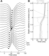
Field potentials (FPs) reflect neuronal activities in the brain, and often exhibit traveling peaks across recording sites. While traveling FPs are interpreted as propagation of neuronal activity, not all studies directly reveal such propagating patterns of neuronal activation. Neuronal activity is associated with transmembrane currents that form dipoles and produce negative and positive fields. Thereby, FP components reverse polarity between those fields and have minimal amplitudes at the center of dipoles. Although their amplitudes could be smaller, FPs are never flat even around these reversals. What occurs around the reversal has not been addressed explicitly, although those are rationally in the middle of active neurons. We show that sensory FPs around the reversal appeared with peaks traveling across cortical laminae in macaque sensory cortices. Interestingly, analyses of current source density did not depict traveling patterns but lamina-delimited current sinks and sources. We simulated FPs produced by volume conduction of a simplified 2 dipoles' model mimicking sensory cortical laminar current source density components. While FPs generated by single dipoles followed the temporal patterns of the dipole moments without traveling peaks, FPs generated by concurrently active dipole moments appeared with traveling components in the vicinity of dipoles by superimposition of individually non-traveling FPs generated by single dipoles. These results indicate that not all traveling FP are generated by traveling neuronal activity, and that recording positions need to be taken into account to describe FP peak components around active neuronal populations.SIGNIFICANCE STATEMENT Field potentials (FPs) generated by neuronal activity in the brain occur with fields of opposite polarity. Likewise, in the cerebral cortices, they have mirror-imaged waveforms in upper and lower layers. We show that FPs appear like traveling across the cortical layers. Interestingly, the traveling FPs occur without traveling components of current source density, which represents transmembrane currents associated with neuronal activity. These seemingly odd findings are explained using current source density models of multiple dipoles. Concurrently active, non-traveling dipoles produce FPs as mixtures of FPs produced by individual dipoles, and result in traveling FP waveforms as the mixing ratio depends on the distances from those dipoles. The results suggest that not all traveling FP components are associated with propagating neuronal activity.
Keywords: cortical layer; current source density; local field potential; macaque; traveling wave; volume conduction.
Copyright © 2021 the authors.
Figures


Similar articles
-
Primary Generators of Visually Evoked Field Potentials Recorded in the Macaque Auditory Cortex.J Neurosci. 2017 Oct 18;37(42):10139-10153. doi: 10.1523/JNEUROSCI.3800-16.2017. Epub 2017 Sep 18. J Neurosci. 2017. PMID: 28924008 Free PMC article.
-
Generation of field potentials and modulation of their dynamics through volume integration of cortical activity.J Neurophysiol. 2015 Jan 1;113(1):339-51. doi: 10.1152/jn.00914.2013. Epub 2014 Oct 1. J Neurophysiol. 2015. PMID: 25274348 Free PMC article.
-
Slow-Wave Activity in the S1HL Cortex Is Contributed by Different Layer-Specific Field Potential Sources during Development.J Neurosci. 2019 Nov 6;39(45):8900-8915. doi: 10.1523/JNEUROSCI.1212-19.2019. Epub 2019 Sep 23. J Neurosci. 2019. PMID: 31548234 Free PMC article.
-
Near- and far-fields: source characteristics and the conducting medium in neurophysiology.J Clin Neurophysiol. 1997 Sep;14(5):429-42. doi: 10.1097/00004691-199709000-00009. J Clin Neurophysiol. 1997. PMID: 9415390 Review.
-
Volume conduction, waveform analysis, and near- and far-field potentials.Handb Clin Neurol. 2019;160:23-37. doi: 10.1016/B978-0-444-64032-1.00002-3. Handb Clin Neurol. 2019. PMID: 31277851 Review.
Cited by
-
Site-dependent shaping of field potential waveforms.Cereb Cortex. 2023 Mar 21;33(7):3636-3650. doi: 10.1093/cercor/bhac297. Cereb Cortex. 2023. PMID: 35972425 Free PMC article.
-
Perceptual echoes as travelling waves may arise from two discrete neuronal sources.Neuroimage. 2023 May 15;272:120047. doi: 10.1016/j.neuroimage.2023.120047. Epub 2023 Mar 29. Neuroimage. 2023. PMID: 37001836 Free PMC article.
-
Sequentially activated discrete modules appear as traveling waves in neuronal measurements with limited spatiotemporal sampling.Elife. 2024 Mar 7;12:RP92254. doi: 10.7554/eLife.92254. Elife. 2024. PMID: 38451063 Free PMC article.
-
Theoretical considerations and supporting evidence for the primary role of source geometry on field potential amplitude and spatial extent.Front Cell Neurosci. 2023 Mar 30;17:1129097. doi: 10.3389/fncel.2023.1129097. eCollection 2023. Front Cell Neurosci. 2023. PMID: 37066073 Free PMC article. Review.
-
Laminar pattern of sensory-evoked dynamic high-frequency oscillatory activity in the macaque auditory cortex.Cereb Cortex. 2024 Aug 1;34(8):bhae338. doi: 10.1093/cercor/bhae338. Cereb Cortex. 2024. PMID: 39128941 Free PMC article.
References
Publication types
MeSH terms
Grants and funding
LinkOut - more resources
Full Text Sources
Miscellaneous
