. 2021 Jul 29;11(1):15454.
doi: 10.1038/s41598-021-94600-y.

A bioimpedance-based monitor for real-time detection and identification of secondary brain injury

Affiliations

A bioimpedance-based monitor for real-time detection and identification of secondary brain injury

Alicia Everitt et al. Sci Rep. .

Abstract

Secondary brain injury impacts patient prognosis and can lead to long-term morbidity and mortality in cases of trauma. Continuous monitoring of secondary injury in acute clinical settings is primarily limited to intracranial pressure (ICP); however, ICP is unable to identify essential underlying etiologies of injury needed to guide treatment (e.g. immediate surgical intervention vs medical management). Here we show that a novel intracranial bioimpedance monitor (BIM) can detect onset of secondary injury, differentiate focal (e.g. hemorrhage) from global (e.g. edema) events, identify underlying etiology and provide localization of an intracranial mass effect. We found in an in vivo porcine model that the BIM detected changes in intracranial volume down to 0.38 mL, differentiated high impedance (e.g. ischemic) from low impedance (e.g. hemorrhagic) injuries (p < 0.001), separated focal from global events (p < 0.001) and provided coarse 'imaging' through localization of the mass effect. This work presents for the first time the full design, development, characterization and successful implementation of an intracranial bioimpedance monitor. This BIM technology could be further translated to clinical pathologies including but not limited to traumatic brain injury, intracerebral hemorrhage, stroke, hydrocephalus and post-surgical monitoring.


Conflict of interest statement

R.J.H. and P.K.M. are co-inventors on US Patent # 8,764,672 B2: System, method and device for monitoring the condition of an internal organ. Scope of patent covered in manuscript: Use of intracranial electrode to overcome high impedance skull. RyTek Medical Inc. is a startup spun out of Dartmouth College and solely owned by R.J.H. Rytek Medical provided partial funding for this work through an NIH STTR Phase 1 grant (#1R41NS100313-01) sub-award made to Dartmouth College. All other authors declare no competing interests.

Figures

Figure 1
Figure 1
Bioimpedance monitoring (BIM) system concept, setup, testing and characterization. (a) Current and voltage schematic for tetrapolar (four-point) driven system. Two leads are on the scalp (I+ and V+) and two placed intracranial (I and V). (b) Eight spatial sensitivity sectors created through rotating impedance channels and controlling the resulting electrical field. (c) CT scan of a gelatin phantom used to validate minimal artifact from selected biocompatible Ag/AgCl electrodes. (d) Custom analog front end developed for the BIM system with corresponding inputs and outputs. (e) Intracranial (top) and scalp surface (bottom) electrodes. The top image shows a sagittal view of the deep brain stimulation (DBS) electrode array coupled to the intracranial pressure (ICP) sensor lead in a pig. The bottom two electrodes were used for impedance sensing within the BIM system. The bottom image shows a segmentation of the surface electrodes (black) overlaid on a 3D reconstruction of a fully instrumented pig (blue). (f) The bioimpedance response to ischemic (top) and hemorrhagic (bottom) changes in tissue, potentially enabling differentiation between the two injury types.
Figure 2
Figure 2
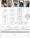
Surgical implementation and system diagram. (a) From left to right: AxiEM navigation and fiducial registration being used to enable precise neurosurgical instrumentation. Top-view of an instrumented pig displaying the scalp surface electrodes, the cranial bolts, the electrode leads, and the three Touhy–Borst adapters securing the two Fogarty catheters and the DBS/ICP lead. The pig successfully setup within the bore of a CT scanner. The instrumentation located at the head of the pig including two syringe pumps, the AFE and the data acquisition unit (DAQ). Lastly, the full system including pig, electrodes, control computers and all supporting hardware in the operating room. (b) Block diagram showing the relationship between all devices in a full test setup, including the electrical impedance acquisition (EIA) system. (c) Protocol used for testing of BIM system with each phase broken down including the two injury types, timings and volumes. Orange and blue traces are ICP and Z, respectively, from a consistent channel across Pig 1. Volume changes can be seen clearly as discrete steps in the ICP curves.
Figure 3
Figure 3
Computed tomography imaging integration and precise capture of evolving intracranial injury. (a) Axial, sagittal and coronal views of cross-sectional masks of the brain created in Mimics. Images spatially advance left to right. (b) 3D segmentation of the same brain generated from interpolation between masks. (c) Segmented intracranial brain volumes for all pigs. (d) oronal view of inflating Fogarty balloon from 0 to 1.2 mL volume. (e) Coronal view of injected autologous blood from 0 to 1.2 mL volume. (f) Stealth navigation surgical plan used for precise placement of the three intracranial instruments, enabled through registration with pre-operative images. (g) 3D reconstruction of post-op intracranial space with three catheters in place and segmented for localization. (h) ICP response summaries across pigs (n = 9) for each protocol phase. Error bars represent  ± one standard deviation. Note the ICP increases as volume increases for balloon inflation and blood injection.
Figure 4
Figure 4
Initial differences in impedance behavior between inflation and hematoma. (a) All collected traces from one pig: eight impedance channels and all Biopac physiologic signals. Sync Traces show linear stage activation for each Mass Effect injection, spaced 5 min apart. Each ICC check occurs 2 min following Mass Effect. CT acquisition followed ICC, with precise timing of the manual acquisition captured through a custom sync button. All Biopac signals are shown in seconds. High noise sections on impedance channels are associated with data recorded during active acquisition of a CT and these artifacts are removed prior to data analysis, as described in Supplementary Method 1. (b) ICP (orange) and impedance (blue) for all animals and both injuries across a single electrode. Pearson’s correlation coefficients and DI represented for each animal for the presented trace. Impedance y-axes are normalized within each animal between injury types.
Figure 5
Figure 5
Identification and differentiation of secondary brain injury. (a) ΔZ compared between injury types across all channels within a single pig. Missing channel (5, blood) is a filtered trace. (b) Change in impedance from baseline of de-trended volume balloon inflation. Threshold for detection determined from SNR with a 10 × safety factor (7.1 Ω) and represented by the horizontal red line. Impedance successfully detected ICV change in all nine pigs. (c) Change in ICP successfully differentiates a volumetric event from baseline, however cannot discriminate between injury type (Supplementary Figure 8). (d) Discriminatory Index significantly differentiates the type of event (injury) occurring.
Figure 6
Figure 6
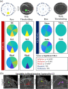
Localization between focal and global events. (a) Colormaps of normalized change in impedance (nΔZ) for each event across all pigs (caxis: 0–1). Raw maps show the mean nΔZ for all elements, while threshold maps display a discrete differentiation between both focal and global events and between ischemic and hemorrhagic injuries. A threshold approach was heuristically determined with thresholds of nΔZ < 13 and nΔZ > 23. Should any element satisfy one of these thresholds, the binary map identifies the minimum or maximum element as the discrete focal injury element for hemorrhage or model ischemia, respectively. Any event with all nΔZ values between 13<nΔZ<23 were categorized as global. Inclusion was located in Element 3. Only focal events presented an element’s ‘sector’ as a significant effect in a mixed model. (b) Display of some of the variabilities present in the hematoma model captured by the CT scan, competing with focal localization ability. From left to right: induced air during blood injection, pooling of blood in the olfactory ventricles (unique to pigs), anterior blood tracking, posterior ventricular tracking down to the spinal cord (most common).
Figure 7
Figure 7
Focal versus global differentiation within and across pigs. (a) Change in impedance between focal (balloon volume change) and global (euthanasia induced brain death) intracranial events within each pig. Nine out of nine pigs showed significant difference in variance (Levene’s) between focal and global events (*p < 0.05; **p < 0.01; ***p < 0.001). (b) Comparison of variance between change in Z for all elements within all pigs between focal and global events shows significant difference. (c) If all elements are averaged into a single-value variance within each pig for each event, the single value variance significantly differentiates focal from global injury (Welch’s t-test to account for unequal variance). (d) Analysis of means for the standard deviation of impedance change for each event of the protocol shows differentiating trends and significant differences from the mean.

References

    1. Carney N, et al. Guidelines for the management of severe traumatic brain injury, Fourth Edition. Neurosurgery. 2016;80:1. - PubMed
    1. Simon DW, et al. The far-reaching scope of neuroinflammation after traumatic brain injury. Nat. Rev. Neurol. 2017;13:171–191. doi: 10.1038/nrneurol.2017.13. - DOI - PMC - PubMed
    1. Rangel-Castilla L, Rangel-Castillo L, Gopinath S, Robertson CS. Management of intracranial hypertension. Neurol. Clin. 2008;26:521–541. doi: 10.1016/j.ncl.2008.02.003. - DOI - PMC - PubMed
    1. Doberstein CE, Hovda DA, Becker DP. Clinical considerations in the reduction of secondary brain injury. Ann. Emerg. Med. 1993;22:993–997. doi: 10.1016/S0196-0644(05)82740-4. - DOI - PubMed
    1. Feigin VL, Barker-Collo S, Krishnamurthi R, Theadom A, Starkey N. Epidemiology of ischaemic stroke and traumatic brain injury. Best Pract. Res. Clin. Anaesthesiol. 2010;24:485–494. doi: 10.1016/j.bpa.2010.10.006. - DOI - PubMed

Publication types