. 2021 Aug 4;12(1):4701.
doi: 10.1038/s41467-021-25036-1.

Plastic and low-cost axial zero thermal expansion alloy by a natural dual-phase composite

Affiliations

Plastic and low-cost axial zero thermal expansion alloy by a natural dual-phase composite

Chengyi Yu et al. Nat Commun. .

Abstract

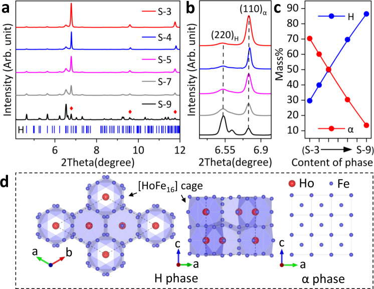
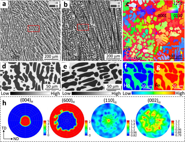
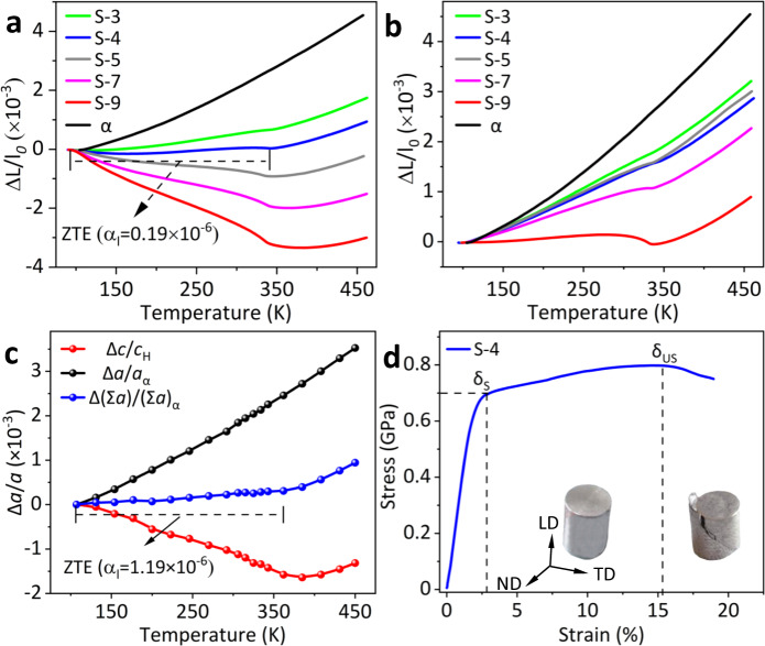
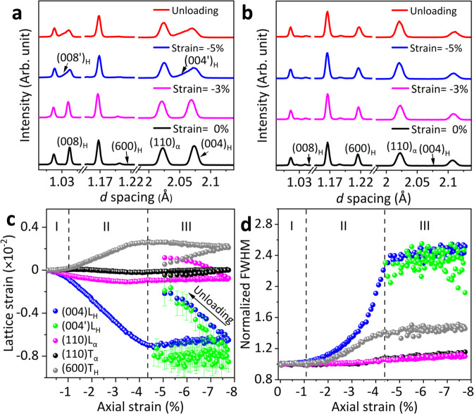
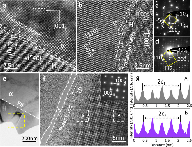
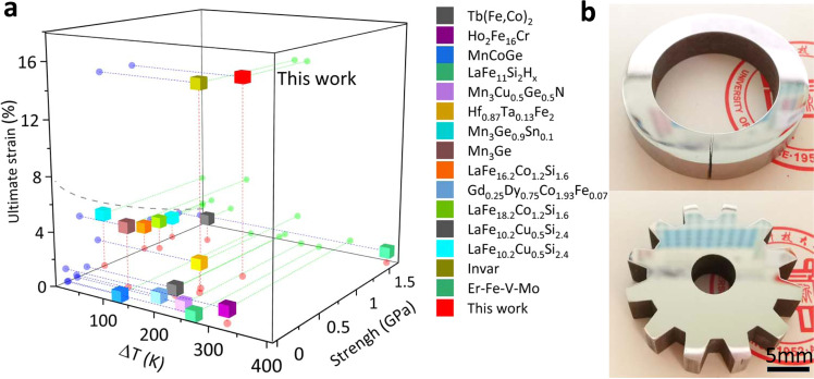
Zero thermal expansion (ZTE) alloys possess unique dimensional stability, high thermal and electrical conductivities. Their practical application under heat and stress is however limited by their inherent brittleness because ZTE and plasticity are generally exclusive in a single-phase material. Besides, the performance of ZTE alloys is highly sensitive to change of compositions, so conventional synthesis methods such as alloying or the design of multiphase to improve its thermal and mechanical properties are usually inapplicable. In this study, by adopting a one-step eutectic reaction method, we overcome this challenge. A natural dual-phase composite with ZTE and plasticity was synthesized by melting 4 atom% holmium with pure iron. The dual-phase alloy shows moderate plasticity and strength, axial zero thermal expansion, and stable thermal cycling performance as well as low cost. By using synchrotron X-ray diffraction, in-situ neutron diffraction and microscopy, the critical mechanism of dual-phase synergy on both thermal expansion regulation and mechanical property enhancement is revealed. These results demonstrate that eutectic reaction is likely to be a universal and effective method for the design of high-performance intermetallic-compound-based ZTE alloys.


Conflict of interest statement

The authors declare no competing interests.

Figures

Fig. 1
Fig. 1. Phase and crystal structures.
a, b High-resolution synchrotron X-ray diffraction profiles for S-3 to S-9 (λ = 0.23991 Å), the marked red diamond is the α phase. c The mass fractions of H and α in S-3 to S-9 are determined via Rietveld refinements. d Crystal structures of H and α phase, respectively.
Fig. 2
Fig. 2. Microstructures of the ZTE alloy.
ab, de The morphology of the as-cast S-4 alloy confirmed by electro-probe microanalyzer (EPMA) in TD (transverse direction)-ND (normal direction) plane (a) and LD (loading direction)-TD plane (b), respectively. (d) and (e) are enlarged regions in (a) and (b) marked with a red box. c Electron back-scattered diffraction (EBSD) inverse pole figure of crystal orientation for S-4 inside the TD-ND plane. fg Element mappings of Ho (f) and Fe (g). h Pole figures by neutron diffraction texture analysis for the bulk orientations of (004)H, (600)H, (110)α, and (002)α directions.
Fig. 3
Fig. 3. Thermal expansion and mechanical properties.
a Linear thermal expansion determined by advanced thermo-dilatometer for S-3 to S-9 and iron along with LD. b The in-plane (TD-ND) linear thermal expansion of S-3 to S-9 and iron. c Lattice thermal expansions of α along the a axis, H along the c axis, and S-4 along with LD. d Compressive stress-strain curves of the S-4 with the insets of S-4 ingot during loading.
Fig. 4
Fig. 4. Real-time in-situ neutron diffraction studies of S-4 alloy.
a, b In-situ neutron diffraction profiles at the strain of 0%, −3%, −5%, and unloading stage collected in the LD (a) and TD (b), respectively, correspond to I, II, and III stages. c, d Lattice strains (c) and normalized peak FWHMs (d) in LD and TD versus applied compressive strain, respectively.
Fig. 5
Fig. 5. TEM studies of S-4 alloy.
a, b High-resolution transmission electron microscopy (HRTEM) image at the phase interface, oriented to the [001]α zone axis (a) and [11¯0]α zone axis (b), respectively. c, d Selected area electron diffraction (SAED) at the phase interface correspond to Fig. 5a and b, respectively. e The microstructure of the S-4 alloy at the strain of −5% along the loading direction, the white dashed line indicates the phase boundary (PB). f The HRTEM image at the shear band area of the H phase, insert is the SAED at the H phase, oriented to the [010] zone axis. The local shear band is formed after large compressive deformation. g Intensity profile along with LD in A and B zones marked in Fig. 5f.
Fig. 6
Fig. 6. Summary of mechanical and thermal expansion performance.
a A review of critical parameters for the typical (near) zero thermal expansion metallic materials: ultimate strain, strength, and temperature window. Note: Invar is a completely plastic material, for comparison, we used the compressive strength at 15.6% strains here. b Pictures of gear (up) and sealing (down) ring fabricated by the present ZTE alloy (S-4).

References

    1. Mohn P. A century of zero expansion. Nature. 1999;400:18–19. doi: 10.1038/21778. - DOI
    1. Zheng X, et al. Giant negative thermal expansion in magnetic nanocrystals. Nat. Nanotechnol. 2008;3:724–726. doi: 10.1038/nnano.2008.309. - DOI - PubMed
    1. Salvador J, et al. Zero thermal expansion in YbGaGe due to an electronic valence transition. Nature. 2003;425:702–704. doi: 10.1038/nature02011. - DOI - PubMed
    1. Song Y, et al. Magnetic-field-induced strong negative thermal expansion in La(Fe,Al)13. Chem. Mater. 2020;32:7535–7541. doi: 10.1021/acs.chemmater.0c02902. - DOI
    1. Hu J, et al. Adjustable magnetic phase transition inducing unusual zero thermal expansion in cubic RCo2-based intermetallic compounds (R = Rare Earth) Inorg. Chem. 2019;58:5401–5405. doi: 10.1021/acs.inorgchem.9b00480. - DOI - PubMed