Review
. 2021 Oct;8(19):e2100798.
doi: 10.1002/advs.202100798. Epub 2021 Aug 5.

In Vitro Strategies to Vascularize 3D Physiologically Relevant Models

Affiliations
Review

In Vitro Strategies to Vascularize 3D Physiologically Relevant Models

Alessandra Dellaquila et al. Adv Sci (Weinh). 2021 Oct.

Abstract

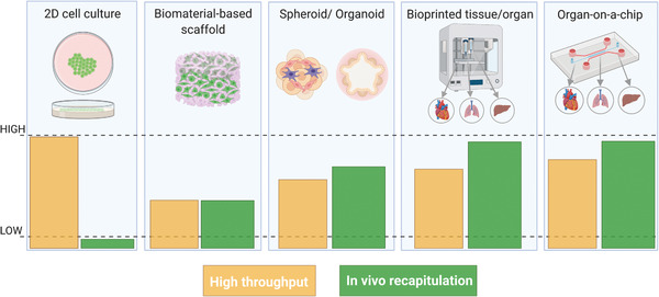
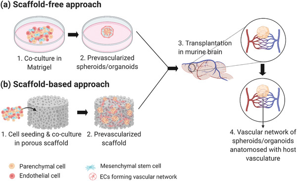
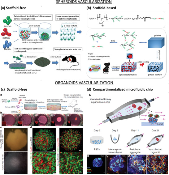
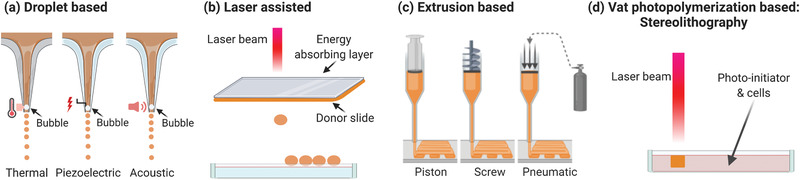
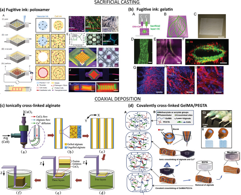
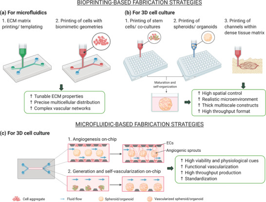
Vascularization of 3D models represents a major challenge of tissue engineering and a key prerequisite for their clinical and industrial application. The use of prevascularized models built from dedicated materials could solve some of the actual limitations, such as suboptimal integration of the bioconstructs within the host tissue, and would provide more in vivo-like perfusable tissue and organ-specific platforms. In the last decade, the fabrication of vascularized physiologically relevant 3D constructs has been attempted by numerous tissue engineering strategies, which are classified here in microfluidic technology, 3D coculture models, namely, spheroids and organoids, and biofabrication. In this review, the recent advancements in prevascularization techniques and the increasing use of natural and synthetic materials to build physiological organ-specific models are discussed. Current drawbacks of each technology, future perspectives, and translation of vascularized tissue constructs toward clinics, pharmaceutical field, and industry are also presented. By combining complementary strategies, these models are envisioned to be successfully used for regenerative medicine and drug development in a near future.

Keywords: 3D cell culture; bioprinting; microfluidics; tissue engineering; vascularization.


Conflict of interest statement

The authors declare no conflict of interest.

Figures

Figure 1
Figure 1
Evolution of tissue engineering platforms from 2D to 3D models. The bottom panel shows the comparison of model throughput versus physiological relevance: the in vivo recapitulation increases when moving from 2D cell cultures to 3D models and the throughput of complex models can be enhanced by means of automated bioprinting processes or parallel microfluidics. Created with BioRender.com.
Figure 2
Figure 2
Physiological properties of the vascular network. a) Anatomical properties and dimensions of the human vasculature. b) Phenotypic heterogeneity of organ‐specific endothelium. c) Differentiated role of endothelial cells during angiogenesis. Created with BioRender.com.
Figure 3
Figure 3
Schematic of the strategies used to vascularize microfluidic‐based models. a,b) Soft lithography and c–f) patterning. a) Membrane‐based vascularized device: i) the fabrication process consists of assembling the microfluidic layers and a porous membrane and the assembled chip with the typical sandwiched structure. b) ECM‐based microfluidic platform: i) the chip usually contains one or more channels filled with ECM proteins that ii) embed the parenchymal and vascular components. c) Templating: i) a matrix is casted around the template equipment (needle, fiber), which is ii) subsequently removed to form the channel. d) Sacrificial molding: i) the patterned template is fabricated and encased in the surrounding matrix, ii) the template is removed, and iii) the device is seeded and perfused. e) Layer‐by‐layer: the modular layers are assembled, for instance, i) by photocrosslinking before ii) the device seeding. f) Bioprinting for microfluidics: usually performed on ECM matrix—eventually bioprinted—in which vascular and parenchymal inks can be used to i) build the tissue before ii) perfusion of the device. Created with BioRender.com.
Figure 4
Figure 4
Microfluidic‐based vascularization strategies: soft lithography (top) and 3D patterning (bottom). a) Liver sinusoid on‐chip fabricated by soft lithography. LSECs and KCs were seeded on the apical side of a PE membrane while HSCs on its basolateral side and HCs on the PDMS substrate (top). Lateral view of the sinusoidal endothelium (bottom): LSECs (green) and KCs (red) on the top and HSCs (yellow) on the bottom of the membrane. Reproduced with permission.[ 73 ] Copyright 2017, The Royal Society of Chemistry. b) ECM‐based vascularized BBB platform: A) HUVECs and fibroblasts were seeded in the vascular channel (VC), and neural cells (astrocytes and neurons) were seeded in the neural channel (NC). The formation of vascular network in the central vascular network channel (VNC) ensured a direct interface between the capillaries and the astrocytes through astrocytic endfeet (B,C: ECs stained in red, astrocytes stained in white). Adapted with permission.[ 66 ] Copyright 2017, Springer Nature. c) Skin‐equivalent platform generated by templating: A,B) The culture device was 3D printed and filled with collagen and fibroblasts to form the dermis layer. After removal of the nylon wires, the hollow channel was seeded with HUVECs to form the capillary, and keratinocytes were cultured on the top of the dermis and exposed to liquid–air interface for cornification of the epidermal layer. C) Perfusion of the device via peristaltic pump. Reproduced with permission.[ 74 ] Copyright 2017, Elsevier Inc. d) Hybrid strategy: 3D printed vascularized proximal tubule model. A,B) The colocalized vascular and renal channels are both 3D printed by using a Pluronic F127‐based fugitive ink within an ECM solution and different designs can be easily printed. C,D) The construct is then seeded with epithelial (green) and endothelial (red) cells. Reproduced with permission.[ 75 ] Copyright 2019, PNAS.
Figure 5
Figure 5
Schematic of the strategies used to vascularize 3D cell culture models. a) Scaffold‐free approach: Coculture with ECs/MSCs to form prevascularized network. b) Scaffold‐based approach: Coculture with ECs/MSCs in porous biomaterials. Both (a) and (b) can be followed by spontaneous vascularization via in vivo transplantation in highly vascularized organ such as the brain. Created with BioRender.com.
Figure 6
Figure 6
Vascularization approaches for spheroids (top) and organoids (bottom). a) Scaffold‐free approach to vascularize spheroids. RNVCMs, HCMECs, and hNDFs were cocultured at optimal cell ratios (70%:15%:15%) and plated into ultralow attachment 96 U‐well plates to form cardiac tissue spheroids. Then, the spheroids were collected and plated in low‐attachment dishes, allowing them to self‐organize into cardiac patch grafts under static conditions. Finally, the cardiac patch grafts were transplanted on the anterior wall of the left ventricle of arhythmic rats to induce spontaneous vascularization. Reproduced with permission.[ 148 ] Copyright 2016, Elsevier Inc. b) Scaffold‐based approach to vascularize spheroids. PLGA activated by 1‐ethyl‐3‐(3‐dimethylaminopropyl) carbodiimide hydrochloride (EDC) and crosslinked with adipic dihydrazide, followed by lyophilization forms porous hydrogel. Seeding of ASCs onto hydrophilic surface induced cell aggregations, which resulted in ASC‐spheroids. Then, the spheroids were transplanted in the dorsum of nude mice to induce spontaneous vascularization. Reproduced with permission.[ 147 ] Copyright 2017, Elsevier Inc. c) Scaffold‐free approach to vascularize organoids: a) Schematic representation of the paper's strategy: hiPSCs, hMSCs, and HUVECs cocultured on Matrigel to form liver organoids, which were transplanted into mice to induce spontaneous vascularization. b) Observation of cells in coculture overtime. Organoids formed within 72 h. c) Observation of hiPSC‐organoids (top panel) and conventional 2D cultures (bottom panel). Scale bar = 1 mm. d) Confocal images showing the presence of hiPSC‐derived hepatic endoderm cells (green) and HUVECs (red) inside liver organoids (left panel), or HUVECs (green) and hMSCs (red) inside hiPSC‐derived organoids. Scale bar = 100 µm. Adapted with permission.[ 117 ] Copyright 2013, Springer Nature. d) Compartmentalized microfluidic‐based hybrid strategy: A) Kidney organoids were cultured in ECM substrate housed inside a perfusable millifluidic chip, subjected to controlled fluidic shear stress. B–E) Confocal 3D observations showing vascular markers in whole‐mount organoids, cultured under static U‐well, static, low‐FSS, and high‐FSS conditions. Scale bars = 100 µm. Adapted with permission.[ 137 ] Copyright 2019, Springer Nature.
Figure 7
Figure 7
Schematic of bioprinting methods. a) Inkjet‐based bioprinting involves the formation of droplets of bioink by generating bubbles in the tip of the printer through thermal, piezoelectric, or acoustic energy. b) Laser‐assisted bioprinting is also based on the generation of droplets of bioink by the incidence of a laser beam on an energy absorbing layer coupled with a donor slide constituted of bioink. The droplets are then recovered on a dedicated platform. c) Extrusion is the most commonly used method; the ink is pressed through the nozzle either with a piston, a screw, or using pneumatic pressure. d) Vat photopolymerization requires the presence of a photoinitiator to cure the polymer loaded with cells. Created with Biorender.com.
Figure 8
Figure 8
Bioprinting‐based vascularization strategies: sacrificial casting (top) and coaxial deposition (bottom). a) Bioprinting of thick vascularized tissues with sacrificial poloxamer: A) Manufacturing process in four steps: i) printing of the sacrificial poloxamer‐thrombin biomaterial bioink and of cell‐laden gelating bioink with endothelial cells; ii) casting of the gelatin/fibrinogen/transglutaminase that interacts with the thrombin diffused from the printed biomaterial causing gelification; iii) removal of the poloxamer by cooling down leading to empty channels; iv) perfusion of the channels with cell media that results in endothelialization of the channels. Three cell types were incorporated: B) HUVECs, C) hNDFs, and D) hMSCs. (Scale bar: 50 µm.) E) Cell viability and mechanical properties of the construct are affected by gelatin preprocessing temperature. hMSC‐laden bioink F) immediately after printing and G) after 3 days. H–K) Images of the bioconstruct. H) Sacrificial bioink colored in red and cell‐laden bioink in green. (Scale bar: 2 mm.) I) Bright‐field image from top. (Scale bar: 50 µm.) J) Construct in a perfusion chamber and K,L) cross‐sections. (Scale bar: 5 mm.) Reproduced with permission.[ 95 ] Copyright 2016, PNAS. b) Bioprinting of thick cardiac patches with sacrificial gelatin. A) Two bioinks composed of decellularized omentum tissue (OM) + cardiomyocytes differentiated form iPSCs (CM) and sacrificial gelatin + endothelial cells (ECs). B) 3D‐ model of the cardiac patch. C) Printed cardiac patch. D–F) Fluorescence images of the printed cardiac patch with the ECs (green), CM (purple), and fibroblasts (red). (Scale bars: 100, 500 and 100 µm, respectively). The cardiac patch was implanted between two layes of the rat omentum and then explanted for analysis. G‐I) Fluorescence images of the explanted patch showing the sarcomeric actin of the CM in red and nuclei in blue. (Scale bars from left to right: 100, 50, 25 µm). Adapted with permission.[ 190 ] Copyright 2019, WILEY‐VCH. Copyright 2019, The Authors. Published by Wiley‐VCH. c) Coaxial bioprinting of 3D hydrogels with microchannels using alginate: a) Schematics of the coaxial nozzle in which alginate and CaCl2 are co‐injected to form b) channels with an inner layer of ionically crosslinked alginate surrounded by ungelled alginate. c) Several channels are printed in parallel and then d) immersed in a bath with CaCl2 to promote e) gelation of the noncrosslinked alginate. f) This step is repeated several times to create a 3D construct. Reproduced with permission.[ 193 ] Copyright 2015, Elsevier Inc. d) Multilayer coaxial bioprinting of perfusable 3D constructs with a blend bioink: A) The bioink gels through ionical crosslink of alginate with Ca2+ and photocrosslink of GelMA and polyethylene glycol (PEGMA) exposed to UV irradiation. B) Schematics of the coaxial nozzle in which the blend bioink is injected in between CaCl2 solution to cause immediate alginate gelation. After UV irradiation, the alginate is removed in contact with EDTA and the construct placed in cell culture medium. C‐I) Multilayered coaxial nozzles and II) schematics of the channel formation. Reproduced with permission.[ 195 ] Copyright 2016, Elsevier Inc.
Figure 9
Figure 9
Hybrid strategies for vascularization. The hybrid approaches are divided into a,b) bioprinting‐based and c) microfluidic‐based. The main advantages of the application of these fabrication strategies for each model are shown in the green panels. Created with BioRender.com.

References

    1. Hu C., Chen Y., Tan M. J. A., Ren K., Wu H., Analyst 2019, 144, 4461. - PubMed
    1. Haase K., Kamm R. D., Regener. Med. 2017, 12, 285. - PMC - PubMed
    1. Rouwkema J., Khademhosseini A., Trends Biotechnol. 2016, 34, 733. - PubMed
    1. Jian H., Wang M., Wang S., Wang A., Bai S., Bio‐Des. Manuf. 2018, 1, 45.
    1. Lin D. S. Y., Guo F., Zhang B., Nanotechnology 2019, 30, 024002. - PubMed

Publication types

MeSH terms

LinkOut - more resources