

Generation of Electromagnetic Field by Microtubules
- PMID: 34360980
- PMCID: PMC8348406
- DOI: 10.3390/ijms22158215
Generation of Electromagnetic Field by Microtubules
Abstract
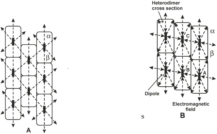
The general mechanism of controlling, information and organization in biological systems is based on the internal coherent electromagnetic field. The electromagnetic field is supposed to be generated by microtubules composed of identical tubulin heterodimers with periodic organization and containing electric dipoles. We used a classical dipole theory of generation of the electromagnetic field to analyze the space-time coherence. The structure of microtubules with the helical and axial periodicity enables the interaction of the field in time shifted by one or more periods of oscillation and generation of coherent signals. Inner cavity excitation should provide equal energy distribution in a microtubule. The supplied energy coherently excites oscillators with a high electrical quality, microtubule inner cavity, and electrons at molecular orbitals and in 'semiconduction' and 'conduction' bands. The suggested mechanism is supposed to be a general phenomenon for a large group of helical systems.
Keywords: helical and axial periodicity; ionization; microtubules; near-field dipole theory; oscillation cavity; water potential layer.
Conflict of interest statement
The authors declare no conflict of interest.
Figures


Similar articles
-
Electric field generated by axial longitudinal vibration modes of microtubule.Biosystems. 2010 May;100(2):122-31. doi: 10.1016/j.biosystems.2010.02.007. Epub 2010 Feb 21. Biosystems. 2010. PMID: 20178826
-
Postulates on electromagnetic activity in biological systems and cancer.Integr Biol (Camb). 2013 Dec;5(12):1439-46. doi: 10.1039/c3ib40166a. Integr Biol (Camb). 2013. PMID: 24166132
-
High-frequency electric field and radiation characteristics of cellular microtubule network.J Theor Biol. 2011 Oct 7;286(1):31-40. doi: 10.1016/j.jtbi.2011.07.007. Epub 2011 Jul 20. J Theor Biol. 2011. PMID: 21782830
-
Biophysical aspects of cancer--electromagnetic mechanism.Indian J Exp Biol. 2008 May;46(5):310-21. Indian J Exp Biol. 2008. PMID: 18697613 Review.
-
Excitation of vibrations in microtubules in living cells.Bioelectrochemistry. 2004 Jun;63(1-2):321-6. doi: 10.1016/j.bioelechem.2003.09.028. Bioelectrochemistry. 2004. PMID: 15110296 Review.
Cited by
-
A Swine Model of Neural Circuit Electromagnetic Fields: Effects of Immediate Electromagnetic Field Stimulation on Cortical Injury.Cureus. 2023 Aug 19;15(8):e43774. doi: 10.7759/cureus.43774. eCollection 2023 Aug. Cureus. 2023. PMID: 37731409 Free PMC article.
-
Precise Electromagnetic Modulation of the Cell Cycle and Its Applications in Cancer Therapy.Int J Mol Sci. 2025 May 7;26(9):4445. doi: 10.3390/ijms26094445. Int J Mol Sci. 2025. PMID: 40362682 Free PMC article. Review.
-
Simultaneity of consciousness with physical reality: the key that unlocks the mind-matter problem.Front Psychol. 2023 Sep 28;14:1173653. doi: 10.3389/fpsyg.2023.1173653. eCollection 2023. Front Psychol. 2023. PMID: 37842692 Free PMC article.
-
Modeling non-genetic information dynamics in cells using reservoir computing.iScience. 2024 Mar 28;27(4):109614. doi: 10.1016/j.isci.2024.109614. eCollection 2024 Apr 19. iScience. 2024. PMID: 38632985 Free PMC article.
References
-
- Fröhlich H. Bose condensation of strongly excited longitudinal electric modes. Phys. Lett. A. 1968;26:402–403. doi: 10.1016/0375-9601(68)90242-9. - DOI
-
- Fröhlich H. Long-range coherence and energy storage in biological systems. Int. J. Quantum Chem. 1968;2:641–649. doi: 10.1002/qua.560020505. - DOI
-
- Fröhlich H. Quantum mechanical concepts in biology. In: Marois M., editor. Theoretical Physics and Biology, Proceedings of The First International Conference on Theoretical Physics and Biology, Versailles, France, 26–30 June 1967. North Holland Publishing Co.; North Holland, Amsterdam: 1969. pp. 13–22.
-
- Fröhlich H. The biological effects of microwaves and related questions. In: Marton L., Marton C., editors. Advances in Electronics and Electron Physics. Volume 53. Elsevier; Amsterdam, The Netherlands: Academic Press; New York, NY, USA: London, UK: Toronto, ON, Canada: Sydney, Australia: San Francisco, CA, USA: 1980. pp. 85–152. - DOI
-
- Pokorný J., Wu T.-M. Biophysical Aspects of Coherence and Biological Order. Springer; Berlin/Heidelberg, Germany: New York, NY, USA: Academia; Prague, Czech Republic: 1998.
MeSH terms
LinkOut - more resources
Full Text Sources
Medical
