. 2021 Aug 1;14(15):4308.
doi: 10.3390/ma14154308.

Evaluation of Stresses on Implant, Bone, and Restorative Materials Caused by Different Opposing Arch Materials in Hybrid Prosthetic Restorations Using the All-on-4 Technique

Affiliations

Evaluation of Stresses on Implant, Bone, and Restorative Materials Caused by Different Opposing Arch Materials in Hybrid Prosthetic Restorations Using the All-on-4 Technique

Feras Haroun et al. Materials (Basel). .

Abstract

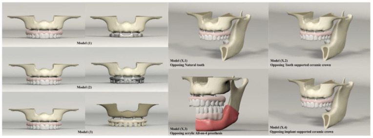
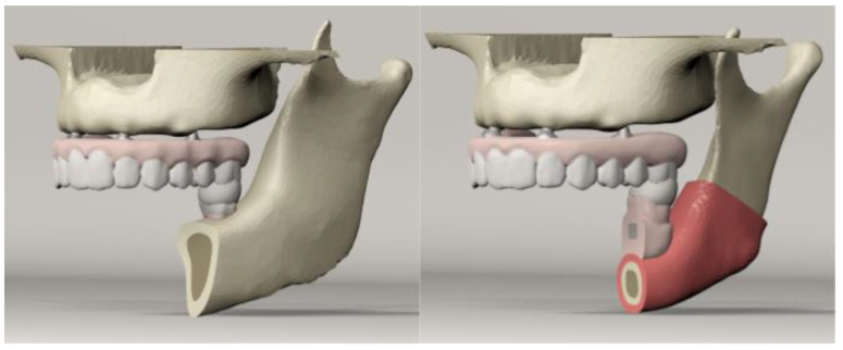
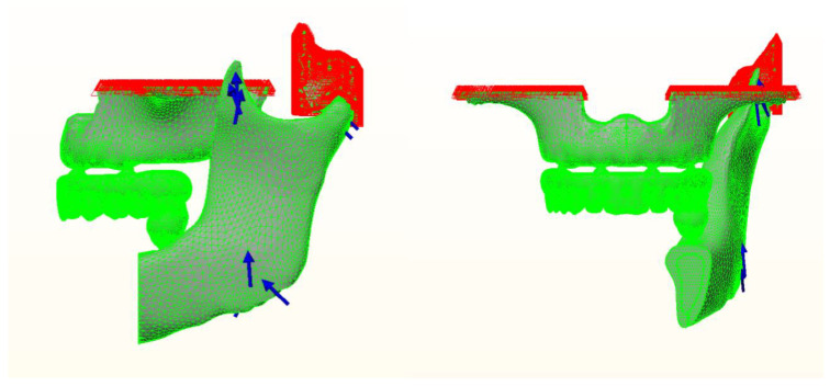
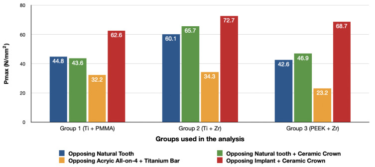
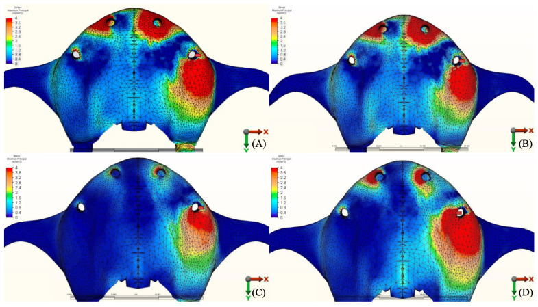
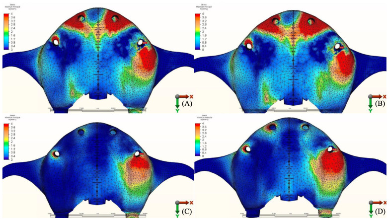
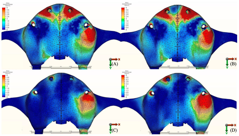
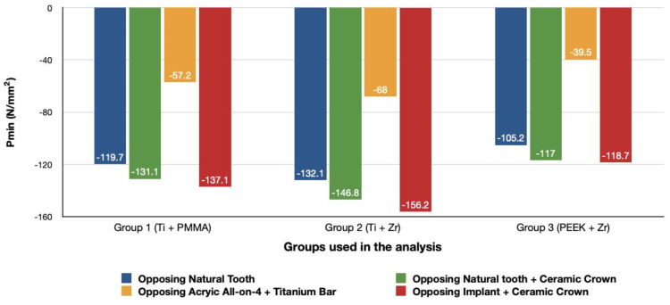
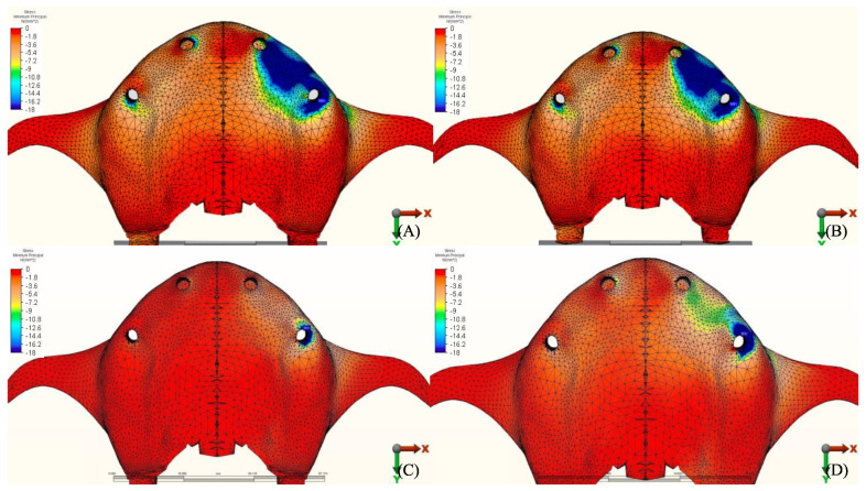
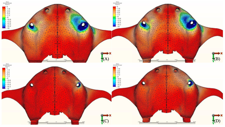
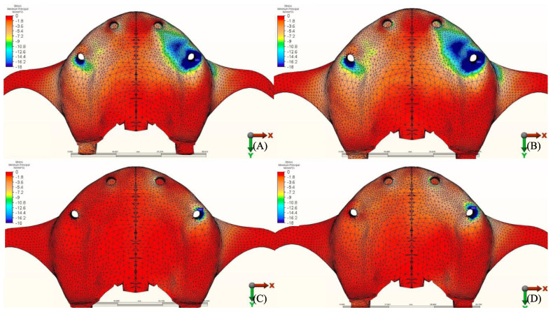
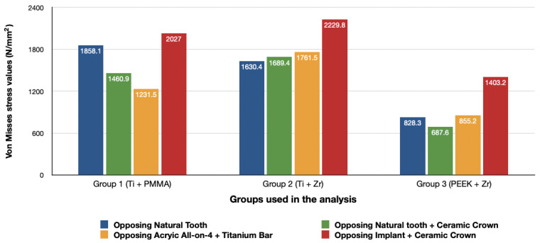
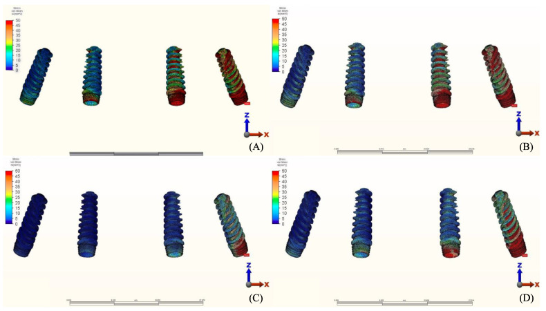
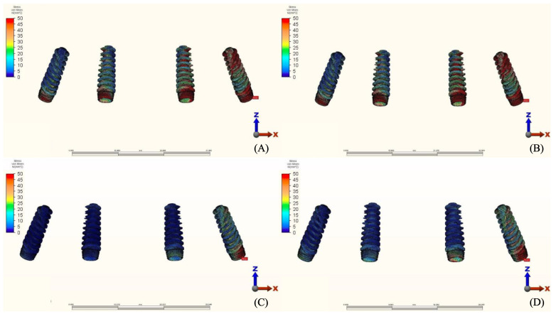
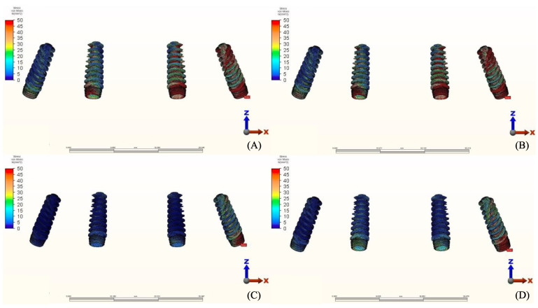
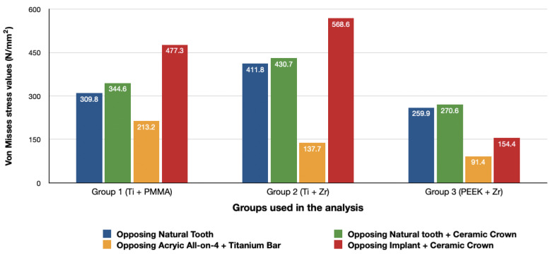
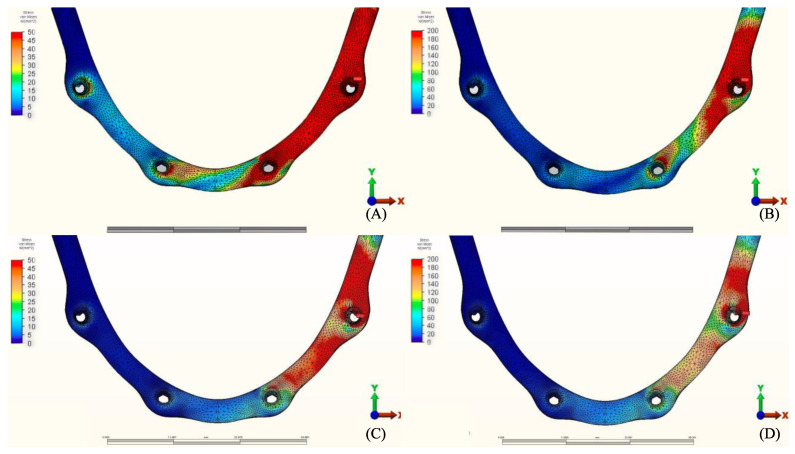
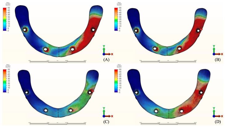
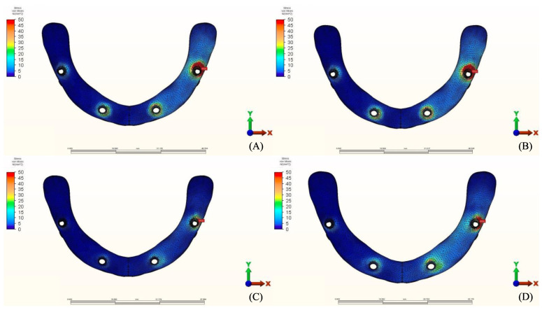
The long-term success of dental implants is greatly influenced by the use of appropriate materials while applying the "All-on-4" concept in the edentulous jaw. This study aims to evaluate the stress distribution in the "All-on-4" prosthesis across different material combinations using three-dimensional finite element analysis (FEA) and to evaluate which opposing arch material has destructive effects on which prosthetic material while offering certain recommendations to clinicians accordingly. Acrylic and ceramic-based hybrid prosthesis have been modelled on a rehabilitated maxilla using the "All-on-4" protocol. Using different materials and different supports in the opposing arch (natural tooth, and implant/ceramic, and acrylic), a multi-vectorial load has been applied. To measure stresses in bone, maximum and minimum principal stress values were calculated, while Von Mises stress values were obtained for prosthetic materials. Within a single group, the use of an acrylic implant-supported prosthesis as an antagonist to a full arch implant-supported prosthesis yielded lower maximum (Pmax) and minimum (Pmin) principal stresses in cortical bone. Between different groups, maxillary prosthesis with polyetheretherketone as framework material showed the lowest stress values among other maxillary prostheses. The use of rigid materials with higher moduli of elasticity may transfer higher stresses to the peri implant bone. Thus, the use of more flexible materials such as acrylic and polyetheretherketone could result in lower stresses, especially upon atrophic bones.

Keywords: All-on-4®; finite element analysis; hybrid prosthesis; implant.


Conflict of interest statement

The authors declare no conflict of interest.

Figures

Figure 1
Figure 1
Maxillary and mandibular models used in the study.
Figure 2
Figure 2
Spherical solid material simulating foodstuff located on the left first molar region.
Figure 3
Figure 3
Boundary conditions and force directions used in the analysis.
Figure 4
Figure 4
Maximum principal stresses (N/mm2) on cortical bone.
Figure 5
Figure 5
Pmax stress distribution in cortical bone for group 1, titanium bar with acrylic teeth. (A) Model 1.1, opposing natural tooth. (B) Model 1.2, opposing tooth-supported full ceramic crown. (C) Model 1.3, opposing acrylic prosthesis with titanium framework. (D) Model 1.4, opposing implant-supported full ceramic crown.
Figure 6
Figure 6
Pmax stress distribution in cortical bone for group 2, titanium bar with resin composite gingiva and ceramic superstructure with zirconium (Toronto bridge). (A) Model 2.1, opposing natural tooth. (B) Model 2.2, opposing tooth-supported full ceramic crown. (C) Model 2.3, opposing acrylic prosthesis with titanium framework. (D) Model 2.4, opposing implant-supported full ceramic crown.
Figure 7
Figure 7
Pmax stress distribution in cortical bone for group 3, PEEK bar with composite resin gingiva and ceramic superstructure with zirconium (Toronto bridge). (A) Model 3.1, opposing natural tooth. (B) Model 3.2, opposing tooth-supported full ceramic crown. (C) Model 3.3, opposing acrylic prosthesis with titanium framework. (D) Model 3.4, opposing implant-supported full ceramic crown.
Figure 8
Figure 8
Minimum principal stresses (N/mm2) on cortical bone.
Figure 9
Figure 9
Pmin stress distribution in cortical bone for group 1, titanium bar with acrylic teeth. (A) Model 1.1, opposing natural tooth. (B) Model 1.2, opposing tooth-supported full ceramic crown. (C) Model 1.3, opposing acrylic prosthesis with titanium framework. (D) Model 1.4, opposing implant-supported full ceramic crown.
Figure 10
Figure 10
Pmin stress distribution in cortical bone for group 2, titanium bar with resin composite gingiva and ceramic superstructure with zirconium (Toronto bridge). (A) Model 2.1, opposing natural tooth. (B) Model 2.2, opposing tooth-supported full ceramic crown. (C) Model 2.3, opposing acrylic prosthesis with titanium framework. (D) Model 2.4, opposing implant-supported full ceramic crown.
Figure 11
Figure 11
Pmin stress distribution in cortical bone for group 3, PEEK bar with composite resin gingiva and ceramic superstructure with zirconium (Toronto bridge). (A) Model 3.1, opposing natural tooth. (B) Model 3.2, opposing tooth-supported full ceramic crown. (C) Model 3.3, opposing acrylic prosthesis with titanium framework. (D) Model 3.4, opposing implant-supported full ceramic crown.
Figure 12
Figure 12
Von Mises stress values on posterior implants under loads.
Figure 13
Figure 13
Implant stress distribution for group 1, titanium bar with acrylic teeth. (A) Model 1.1, opposing natural tooth. (B) Model 1.2, opposing tooth-supported full ceramic crown. (C) Model 1.3, opposing acrylic prosthesis with titanium framework. (D) Model 1.4, opposing implant-supported full ceramic crown.
Figure 14
Figure 14
Implant stress distribution for group 2, titanium bar with resin composite gingiva and ceramic superstructure with zirconium (Toronto bridge). (A) Model 2.1, opposing natural tooth. (B) Model 2.2, opposing tooth-supported full ceramic crown. (C) Model 2.3, opposing acrylic prosthesis with titanium framework. (D) Model 2.4, opposing implant-supported full ceramic crown.
Figure 15
Figure 15
Implant stress distribution for group 3, PEEK bar with composite resin gingiva and ceramic superstructure with zirconium (Toronto bridge). (A) Model 3.1, opposing natural tooth. (B) Model 3.2, opposing tooth-supported full ceramic crown. (C) Model 3.3, opposing acrylic prosthesis with Ti framework. (D) Model 3.4, opposing implant-supported full ceramic crown.
Figure 16
Figure 16
Values of Von Mises stresses on Framework under loads.
Figure 17
Figure 17
Stress distribution in the framework for group 1, titanium bar with acrylic teeth. (A) Model 1.1, opposing natural tooth. (B) Model 1.2, opposing tooth-supported full ceramic crown. (C) Model 1.3, opposing acrylic prosthesis with titanium framework. (D) Model 1.4, opposing implant-supported full ceramic crown.
Figure 18
Figure 18
Stress distribution in the framework for group 2, titanium bar with resin composite gingiva and ceramic superstructure with zirconium (Toronto bridge). (A) Model 2.1, opposing natural tooth. (B) Model 2.2, opposing tooth-supported full ceramic crown. (C) Model 2.3, opposing acrylic prosthesis with titanium framework. (D) Model 2.4, opposing implant-supported full ceramic crown.
Figure 19
Figure 19
Stress distribution in the framework for group 3, PEEK bar with composite resin gingiva and ceramic superstructure with zirconium (Toronto bridge). (A) Model 3.1, opposing natural tooth. (B) Model 3.2, opposing tooth-supported full ceramic crown. (C) Model 3.3, opposing acrylic prosthesis with titanium framework. (D) Model 3.4, opposing implant-supported full ceramic crown.

Similar articles

Cited by

References

    1. Türker N., Büyükkaplan U.S., Sadowsky S.J., Özarsalan M.M. Özarslan Finite Element Stress Analysis of Applied Forces to Implants and Supporting Tissues Using the “All-on-Four” Concept with Different Occlusal Schemes. J. Prosthodont. 2018;28:185–194. doi: 10.1111/jopr.13004. - DOI - PubMed
    1. Geringer A., Diebels S., Nothdurft F.P. Influence of superstructure geometry on the mechanical behavior of zirconia implant abutments: A finite element analysis. Biomed. Tech. Eng. 2014;59:501–506. doi: 10.1515/bmt-2013-0088. - DOI - PubMed
    1. Ferreira M.B., Barão V.A., Faverani L.P., Hipólito A.C., Assunção W.G. The role of superstructure material on the stress distribution in mandibular full-arch implant-supported fixed dentures. A CT-based 3D-FEA. Mater. Sci. Eng. C. 2014;35:92–99. doi: 10.1016/j.msec.2013.10.022. - DOI - PubMed
    1. Papaspyridakos P., Chen C.-J., Chuang S.-K., Weber H.-P., Gallucci G. A systematic review of biologic and technical complications with fixed implant rehabilitations for edentulous patients. Int. J. Oral Maxillofac. Implant. 2012;27:102–110. - PubMed
    1. Fischer K., Stenberg T. Prospective 10-Year Cohort Study Based on a Randomized Controlled Trial (RCT) on Implant-Supported Full-Arch Maxillary Prostheses. Part 1: Sandblasted and Acid-Etched Implants and Mucosal Tissue. Clin. Implant. Dent. Relat. Res. 2011;14:808–815. doi: 10.1111/j.1708-8208.2011.00389.x. - DOI - PubMed

LinkOut - more resources