Review
. 2021 Jul 29;21(15):5153.
doi: 10.3390/s21155153.

Process Variability in Top-Down Fabrication of Silicon Nanowire-Based Biosensor Arrays

Affiliations
Review

Process Variability in Top-Down Fabrication of Silicon Nanowire-Based Biosensor Arrays

Marcel Tintelott et al. Sensors (Basel). .

Abstract

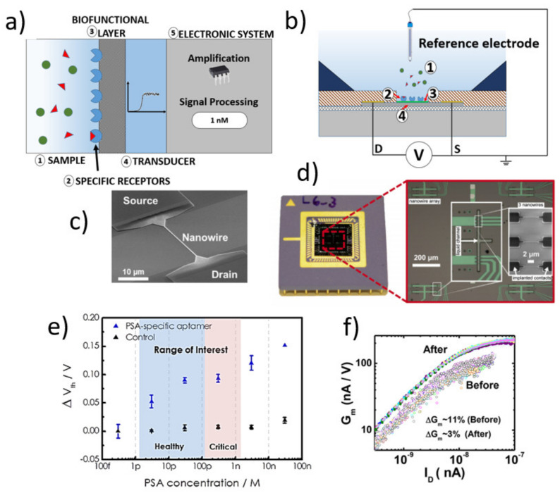
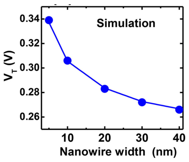
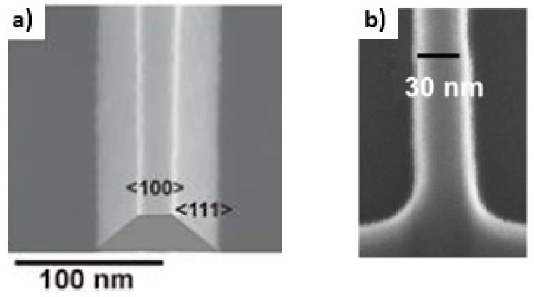
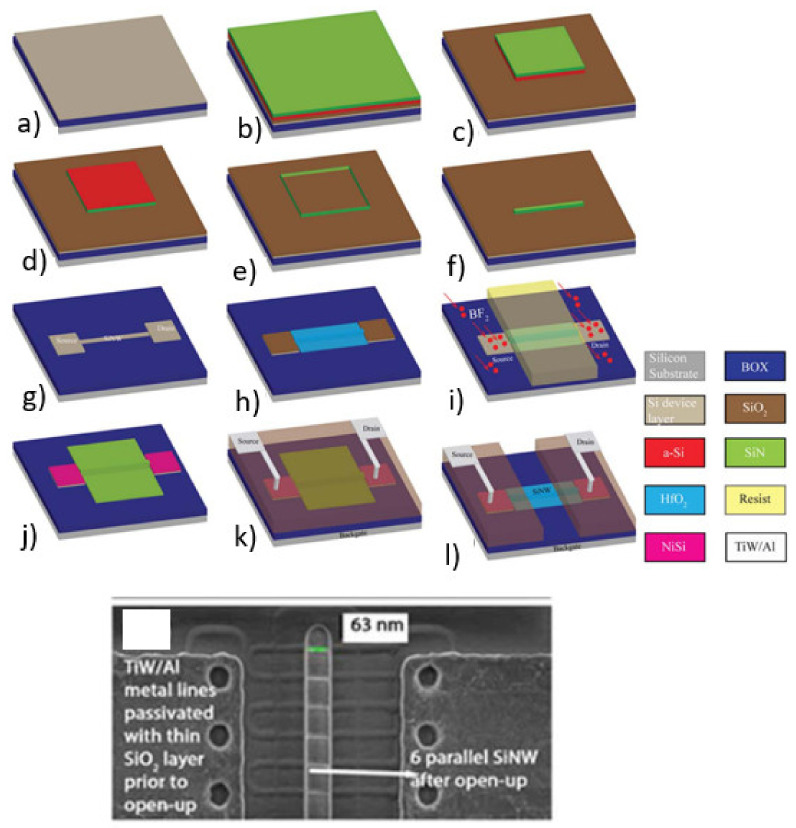
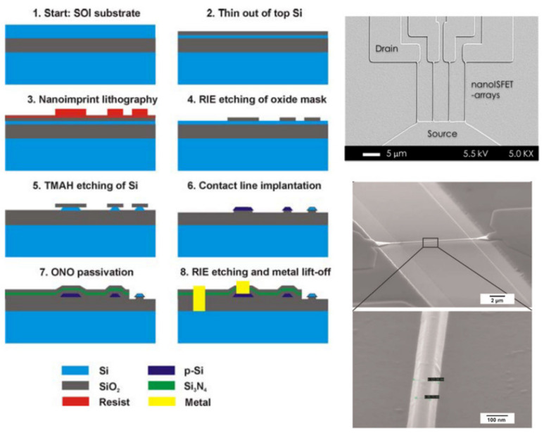
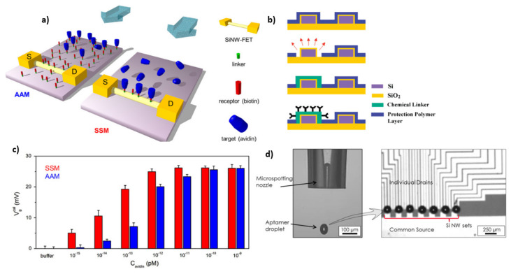
Silicon nanowire field-effect transistors (SiNW-FET) have been studied as ultra-high sensitive sensors for the detection of biomolecules, metal ions, gas molecules and as an interface for biological systems due to their remarkable electronic properties. "Bottom-up" or "top-down" approaches that are used for the fabrication of SiNW-FET sensors have their respective limitations in terms of technology development. The "bottom-up" approach allows the synthesis of silicon nanowires (SiNW) in the range from a few nm to hundreds of nm in diameter. However, it is technologically challenging to realize reproducible bottom-up devices on a large scale for clinical biosensing applications. The top-down approach involves state-of-the-art lithography and nanofabrication techniques to cast SiNW down to a few 10s of nanometers in diameter out of high-quality Silicon-on-Insulator (SOI) wafers in a controlled environment, enabling the large-scale fabrication of sensors for a myriad of applications. The possibility of their wafer-scale integration in standard semiconductor processes makes SiNW-FETs one of the most promising candidates for the next generation of biosensor platforms for applications in healthcare and medicine. Although advanced fabrication techniques are employed for fabricating SiNW, the sensor-to-sensor variation in the fabrication processes is one of the limiting factors for a large-scale production towards commercial applications. To provide a detailed overview of the technical aspects responsible for this sensor-to-sensor variation, we critically review and discuss the fundamental aspects that could lead to such a sensor-to-sensor variation, focusing on fabrication parameters and processes described in the state-of-the-art literature. Furthermore, we discuss the impact of functionalization aspects, surface modification, and system integration of the SiNW-FET biosensors on post-fabrication-induced sensor-to-sensor variations for biosensing experiments.

Keywords: biosensor; device-to-device variation; silicon nanowire field-effect transistor; surface modification; top-down fabrication.


Conflict of interest statement

The authors declare no conflict of interest.

Figures

Figure 1
Figure 1
Schematic overview of different applications of SiNW-FETs. The inner ring shows a schematic illustration of a SiNW-FET and a sensing setup. The outer ring illustrates different applications of SiNW-FETs.
Figure 2
Figure 2
(a) Schematic illustration of an electrical biosensor: The analyte of interest (1) interacts with the specific receptor layer (2), which will be recognized by the biofunctional layer (3). The transducer (4) alters its electrical characteristic, which is read by the electronic system (5). (b) Schematic setup of a biosensor based on SiNW-FETs. (c) scanning electron microscopy (SEM) image of a SiNW and its contacts in the micrometer regime. [Reprinted with permission from [8]. Copyright (2018), Wiley]. (d) Encapsulated SiNW chip with microfluidic structures. [Reprinted with permission from [40]. Copyright (2014), Elsevier]. (e) Dose-response curve of a SiNW-FET to detect PSA using PSA-specific aptamers. [Reprinted with permission from [6]]. (f) Variations of the gm value before and after optimizing the fabrication process to reduce the sensor-to-sensor variations. [Reprinted with permission from [13]. Copyright (2018) American Chemical Society].
Figure 3
Figure 3
The simulation result shows the dependency of the threshold voltage (Vth) on the nanowire width. [Reprinted with permission from [13]. Copyright (2018) American Chemical Society].
Figure 4
Figure 4
SEM images of wet etched (a) [Reprinted with permission from [22]. Copyright (2009), Wiley] and dry etched (b) [Reprinted with permission from [13]. Copyright (2018) American Chemical Society] SiNWs. The wet etched SiNW has a trapezoid structure due to sidewalls with (111) orientation compared to the dry-etched having vertical sidewalls with a (110) orientation.
Figure 5
Figure 5
Illustration of two possible methods to form ohmic feed line contacts. Formation of ohmic contacts close to the NW (a) [Reprinted with permission from [2]] and formation of ohmic contacts on top of silicon feed lines (b) [Reprinted with permission from [27]]. Electrical readout configuration for DC readout of liquid gated FETs (c). Schematic illustration of the impact of drain and source feed line resistance RD and RS on the resulting drain current Id (d).
Figure 6
Figure 6
Schematic view of the electrical equivalent circuit of the SiNW FET in AC-mode. Variation in drain and source capacitance will lead to variations in the output signal. [Reprinted with permission from [8]. Copyright (2018), Wiley].
Figure 7
Figure 7
Illustration of uniform and varying thicknesses of the gate dielectric (a) and simulation results of how the varying thickness influences the subthreshold slope (b). SEM images of varying and uniform gate oxide thickness (c,d). [Reprinted with permission from [13]. Copyright (2018) American Chemical Society].
Figure 8
Figure 8
Schematic process flow to fabricate SiNW-FETs using EBL (top). [Reprinted with permission from [31]. Copyright (2020), American Chemical Society]. SEM image of top-down fabricated SiNW-FETs using EBL (bottom). [Reprinted with permission from [72]. Copyright (2011), AIP].
Figure 9
Figure 9
Process flow of top-down fabrication of SiNWs using STL (top): SOI is used as a starting material (a). Deposition of a tri-layer stack of SiO2, amorphous silicon (a-Si), and silicon nitride (SiN) (b). Selective etching of a-Si using SiN as a hard mask (c). Deposition of a SiN spacer (d). Etching of a-Si using TMAH (e). Removal of the spacers (f). Patterning of drain/source contacts and SiNW (g). Formation of a gate oxide using thermal oxidation of silicon and subsequent HfO2 ALD deposition (h). Ion-implantation to form conductive drain and source regions (i). Formation of nickel silicide (NiSi) ohmic contacts (j). Passivation of feed lines and contact metallization (k). Opening of the gate area (l). [Reprinted with permission from [74]]. SEM picture of the resulting device (bottom). [Reprinted with permission from [74]].
Figure 10
Figure 10
Schematic illustration of the process flow for fabrication of SiNW FETs using NIL (left) [Reprinted with permission from [22]. Copyright (2009), Wiley]. SEM images of wet etched SiNW fabricated using NIL (right) [Reprinted with permission from [29]. Copyright (2010), Wiley, and reprinted with permission from [27]].
Figure 11
Figure 11
Visualization of AAM and SSM modification of SiNW-FETs (a) [Reprinted with permission from [78]. Copyright (2013), Elsevier]. Schematic illustration of a single NW functionalization using a protective polymer layer (b). [Reprinted with permission from [82]. Copyright (2007), American Chemical Society]. Comparison of the signal response of AAM and SSM modified SiNW-FETs (c) [Reprinted with permission from [78]. Copyright (2013), Elsevier]. Micro spotting technique for localized surface modification (d). [Reprinted with permission from [6]].
Figure 12
Figure 12
Schematic illustration of a microfluidic well and different positions of the reference electrode (a). [Reprinted with permission from [27]] Experimental setups for SiNW-FETs using PDMS-based microfluidic channels (b) [Reprinted with permission from [29]. Copyright (2010), Wiley] and (d) [Reprinted with permission from [2]]. Threshold voltage dependency on the position of the reference electrode (c). [Reprinted with permission from [27]].

References

    1. Dincer C., Bruch R., Costa-Rama E., Fernandez-Abedul M.T., Merkoci A., Manz A., Urban G.A., Guder F. Disposable Sensors in Diagnostics, Food, and Environmental Monitoring. Adv. Mater. 2019;31:e1806739. doi: 10.1002/adma.201806739. - DOI - PubMed
    1. Li J., Kutovyi Y., Zadorozhnyi I., Boichuk N., Vitusevich S. Monitoring of Dynamic Processes during Detection of Cardiac Biomarkers Using Silicon Nanowire Field-Effect Transistors. Adv. Mater. Interfaces. 2020;7:2000508. doi: 10.1002/admi.202000508. - DOI
    1. Vacic A., Criscione J.M., Stern E., Rajan N.K., Fahmy T., Reed M.A. Multiplexed SOI BioFETs. Biosens Bioelectron. 2011;28:239–242. doi: 10.1016/j.bios.2011.07.025. - DOI - PMC - PubMed
    1. Zheng G., Patolsky F., Cui Y., Wang W.U., Lieber C.M. Multiplexed electrical detection of cancer markers with nanowire sensor arrays. Nat. Biotechnol. 2005;23:1294–1301. doi: 10.1038/nbt1138. - DOI - PubMed
    1. Cui Y., Wei Q., Park H., Lieber C.M. Nanowire nanosensors for highly sensitive and selective detection of biological and chemical species. Science. 2001;293:1289–1292. doi: 10.1126/science.1062711. - DOI - PubMed

LinkOut - more resources