. 2021 Oct;8(20):e2102274.
doi: 10.1002/advs.202102274. Epub 2021 Aug 16.

In Vivo Clonal Analysis Reveals Development Heterogeneity of Oligodendrocyte Precursor Cells Derived from Distinct Germinal Zones

Affiliations

In Vivo Clonal Analysis Reveals Development Heterogeneity of Oligodendrocyte Precursor Cells Derived from Distinct Germinal Zones

Rui Liu et al. Adv Sci (Weinh). 2021 Oct.

Abstract

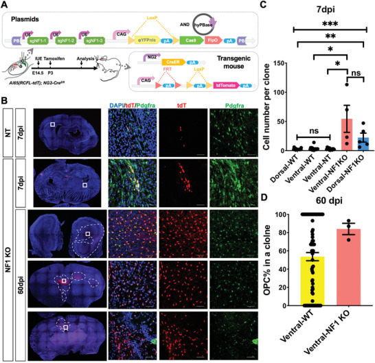
Mounting evidence supports that oligodendrocyte precursor cells (OPCs) play important roles in maintaining the integrity of normal brains, and that their dysfunction is the etiology of numerous severe neurological diseases. OPCs exhibit diverse heterogeneity in the adult brain, and distinct germinal zones of the embryonic brain contribute to OPC genesis. However, it remains obscure whether developmental origins shape OPC heterogeneity in the adult brain. Here, an in vivo clonal analysis approach is developed to address this. By combining OPC-specific transgenes, in utero electroporation, and the PiggyBac transposon system, the lineages of individual neonatal OPCs derived from either dorsal or ventral embryonic germinal zones are traced, and the landscape of their trajectories is comprehensively described throughout development. Surprisingly, despite behaving indistinguishably in the brain before weaning, dorsally derived OPCs continuously expand throughout life, but ventrally derived OPCs eventually diminish. Importantly, clonal analysis supports the existence of an intrinsic cellular "clock" to control OPC expansion. Moreover, knockout of NF1 could circumvent the distinction of ventrally derived OPCs in the adult brain. Together, this work shows the importance of in vivo clonal analysis in studying stem/progenitor cell heterogeneity, and reveals that developmental origins play a role in determining OPC fate.

Keywords: NF1; developmental origin; heterogeneity; homeostasis; in vivo clonal analysis; oligodendrocyte precursor cell.


Conflict of interest statement

The authors declare no conflict of interest.

Figures

Figure 1
Figure 1
Development of PiggyBac transposon‐based in vivo lineage tracing system with single cell resolution. A) Configuration of the PiggyBac transposon reporter system designed in this study. By default, the cells integrated with the PB vector will express a nucleus‐localized yellow fluorescent protein (ΦYFP). The expression of cell‐type specific recombinase removes the ΦYFP coding sequence along with the stop signals (LoxP‐Stop‐LoxP,) and results the expression of EGFP/tdTomato. B) Diagram showing the procedure used to generate labeled OPCs by IUE. C) Diagram showing the anatomical structure of an embryonic mouse brain, wherein the three germinal zones functioning as the developmental origins of OPCs are labeled. D) Representative immunofluorescent staining images of brain sections from NG2‐Cre mouse brains electroporated with the PB: LoxP‐Stop‐LoxP (LSL)‐EGFP reporter. Arrows indicate the cells expressing Pdgfrα (the OPC marker). Dotted circles mark the cells expressing CC1 (the differentiated oligodendrocyte marker). Pα, Pdgfrα. Scale bars, 50 µm. The right panels are the magnifications. Scale bars, 20 µm. E) 3D reconstruction from consecutive brain sections demonstrates the different distribution among OPC lineage cells with distinct origins analyzed at P21. Contours of the boundaries of brain sections, namely: the CC and the lateral ventricle, are marked by colored lines. Green dots represent the labeled oligodendrocyte lineage cells. D, dorsal. V, ventral. R, rostral. C, caudal.
Figure 2
Figure 2
Lineage tracing at the populational level reveals that OPCs with different origins are heterogeneous. A) Diagram showing the anatomical sub‐structures of an adult mouse brain and their abbreviations where labeled OPCs populated. B) The distribution of labeled cells at P21 from the electroporation models as indicated. N = 4 mice for each group. Error bar: mean ± SEM. N = 4 mice for each group. Mann–Whitney test for comparison of group “F”, group “others”. T test for other groups. One‐tailed. *p < 0.05, **< 0.01, ****< 0.0001. C) Representative immunofluorescent staining images of the labeling pattern in the indicated brain areas. Pα, Pdgfrα. Scale bars, 100 µm. D) The numbers of labeled OPC lineage cells from dorsal and ventral germinal zones in the indicated brain areas at P21. N = 4 mice for each group. Error bars: mean ± SEM. T test for group D, L, CC, and Str. Mann–Whitney test for other groups. One‐tailed. E) The differentiation potential of OPCs derived from dorsal or ventral origins. N = 4 mice for all ventral groups. For dorsal groups, N = 3 mice for P21, N = 7 for P60, and N = 4 for P180. Error bars: mean ± SEM. One‐way ANOVA, p = 0.0003 for D, p = 0.0113 for V. Tukey post‐hoc test, **< 0.01, ***< 0.001. F) The proliferation potential of labeled OPCs from dorsal and ventral germinal zones in different brain areas. Ki67 indicates the proliferating cells at P21. Treatment of BrdU for 8 days labeled the proliferating cells at P60. N = 3 mice for each group. Error bars: mean ± SEM. Mann–Whitney test for comparison of the proportion of BrdU positive green cells at P60. T test for others. One‐tailed. *p < 0.05. G) Total numbers of GFP positive cells in dorsally and ventrally electroporated brains harvested at indicated ages. Error bars: mean ± SEM. Two‐way ANOVA, p = 0.0556. Tukey post‐hoc test, *p < 0.05, ***< 0.001. H) Number and proportion of available samples obtained from dorsal and ventral electroporation. The histogram shows how many brains contain cells or not. The pie chart shows how many cells labeled in a brain. The number of mice in each group is shown in the graph.
Figure 3
Figure 3
Development of the system for in vivo clonal analysis of OPCs. A) Diagram showing the scheme for the test in (B) and (C). B) Optimization of the concentration and ratio of plasmids in the IUE experiment. Error bars, ± SEM. C) Titration of tamoxifen dosage for an appropriate number of OPCs labeled initially. Error bars: mean ± SEM. Kruskal–Wallis test, p = 0.0084. Dunn post‐hoc test, *p < 0.05, **< 0.01. D) Representative immunofluorescence image showing a single OPC labeled after 48 h of electroporation. CC, corpus callosum. Ctx, cortex. LV, lateral ventricle. Pir, piriform cortex. Str, striatum. Scale bar, 10 µm. E–G) Representative large clone generated by the labeling system. This clone contained 98 cells, and overstraddled both the gray and white matter. G) 3D reconstruction of the clone from (E,F) built by Neurolucida (MBF). The boundary of the anatomical structures was demarcated. Pα, Pdgfrα. Scale bars in (E): 50 µm. H) Scheme for NND model in (I). The box above shows the plasmids electroporated into the brain. Box below shows the genotype of mice. The diagram of the brain displays three possible labeling patterns. I) NND analysis of OPCs labeled by electroporation. The lines represent the cumulative frequency of the NNDs of the labeled OPCs. The green line represents OPCs expressing EGFP only, the carmine line for OPCs expressing EGFP and tdTomato together, and the gray lines show the simulated random data set.
Figure 4
Figure 4
Clonal analysis via the MADM mouse model reproduces the results from the electroporation models. A) Scheme of MADM‐based in vivo clonal analysis model, illustrating how MADM generates cells with distinct colors. The labeling pattern of the electroporation model is also provided. B) Representative images of a MADM OPC clones clone containing both red and green cells. Labeling of cells was achieved by using NG2‐CreERT transgene. The detailed procedure to perform MADM‐based clonal analysis can be found in Section 4. Pα, Pdgfrα. Scale bars, 50 µm. C) The average size of R/G clones was largely 2‐fold of the R or G clones at 7 days and 18 days post injection. R/G clones contained both red and green cells, while R or G clones only contained red or green cells. Error bars: mean ± SEM. Mann‐Whitney test for data of 7dpi. T test for data of 18dpi. One‐tailed. *p < 0.05. D) The average size of clones from the MADM model as indicated. Of note, G or R clones were smaller than others. Error bars: mean ± SEM. One‐tailed Mann–Whitney test for data of 48 hpi. Kruskal–Wallis test for other groups, p = 0.0587 for 7 dpi, p = 0.1407 for 18dpi. E) The size of R/G clones from the MADM model was comparable to those generated by the electroporation model. Error bars: mean ± SEM. One‐tailed Mann–Whitney test. For the MADM model, there were N = 50, 50, and 22 clones for yellow clones at 48 h, 7dpi, and 18dpi, respectively; N = 8, 12, and 12 clones for G or R clones; and N = 0, 3, and 9 for G/R clones. For the IUE model, there were N = 33 and 153 clones at 7 and 18 dpi, respectively.
Figure 5
Figure 5
The proliferation and differentiation potentials of OPC clones derived from dorsal and ventral germinal zones. A) The average size of clones as indicated. Of note, OPC clones from the ventral origin eventually vanished from the brain. Error bars: mean ± SEM. Two‐way ANOVA followed by Tukey post‐hoc test, *p < 0.05, ****< 0.0001. B) The proportion of OPC in each clone. Error bars: mean ± SEM. Kruskal–Wallis test followed by Dunn post‐hoc test. *p < 0.05, ****< 0.0001. ns, not significant. C) Representative images of an oligodendrocyte derived from ventral OPC expressing CC1, the differentiated oligodendrocyte marker. Scale bars, 10 µm. D) Representative images of an oligodendrocyte derived from ventral OPC expressing MBP, the myelinating oligodendrocyte marker and the staining of Caspr, which is the marker protein of paranodes. Scale bars, 10 µm. E–I) The OPC percentage in each clone from different brain structures. N/A, not applicable, which means no clone was found in these areas of those groups. For dorsal groups, there were N = 15 clones for 24 h, N = 12 for 48 h, N = 16 for 7dpi, N = 12 for 12 dpi, N = 81 for 18 dpi, N = 60 for 60 dpi, and N = 61 for 180 dpi. For ventral groups, there were N = 9 clones for 24 h, N = 27 for 48 h, N = 17 for 7 dpi, N = 5 for 12 dpi, N = 72 for 18 dpi, and N = 89 for 60 dpi.
Figure 6
Figure 6
OPC clones exhibited an integer multiple of the Gaussian unit in the early stage. A–C) Gaussian Fitting of the distribution of the sizes of dorsally derived clones at A) 18 dpi, B) 12 dpi, and C) 7 dpi. The black columns represent the frequency of clone sizes. The dotted lines show the simulated distribution with the integer number as indicated. D–F) The percentage of OPCs in each clone was aligned with the clone size. The gray columns represent the frequency of clone sizes same as that in (A–C). The red dots represent the OPC percentage in each clone. G–I) Gaussian Fitting of frequency distribution of the sizes of ventrally derived clones at G) 18 dpi, H) 12 dpi, and I) 7 dpi. J–L) The percentage of OPCs in each clone was quantified according to the clone size. N number was indicated above the graphs. M) The deduced dividing pattern of dorsally derived OPCs at early stage based on the data from (A–C).
Figure 7
Figure 7
OPC clones can be classified as five subtypes based on their spatial orientations. A) Models of four subtypes of OPC clones based on their shapes. B–E) Representative immunofluorescent images of the four subtypes of clones as indicated. The insets show the zoom‐in image of the clone. Ctx, cortex. CC, corpus callosum. Scale bars, 50 µm. F) The abundance of 5 subtypes of clones along their development. NA, not applicable as no clones were found. G) The abundance of 5 subtypes of clones within different brain structures. CC, corpus callosum. Pir, piriform cortex. See also Videos S1–S4, Supporting Information for the 3D reconstruction of each representative subtype of clones. H) Representative images of a Radial‐subtype clone in the cortex. The staining of neuron‐specific βIII‐Tubulin and Neurofilament‐H delineates the trend of the axons. I) Representative images of a Horizontal‐subtype clone located in the CC. The staining of MBP delineates the distribution of the myelin.
Figure 8
Figure 8
NF1 KO can convert the death of ventrally derived OPCs. A) Configuration of the gene knocking‐out approach mediated by the PiggyBac transposon reporter system and CRISPR‐Cas9 in this study. The expression of cell‐type specific recombinase will remove the ΦYFP coding sequence along with the stop signals (LSL) and result the expression of Cas9 and FlpO on the PB reporter plasmid. The Cre and FlpO recombinases will remove the double stop signals (FSF‐LSL) to label the cells through expression of tdTomato. At the same time, Cas9 and sgRNA controlled by U6 promoters will edit the gene of interest. B) Representative immunofluorescent images of cells electroporated with plasmids carrying tandem sgNT (Non‐targeting sgRNA) or tandem sgNF1 at the indicated age. The white squares in the brain slice map indicate the location of zoom‐in images on the right. Scale bars, 50 µm. C) The average size of clones as indicated. WT means the cells labeled by the previous system. Error bars: mean ± SEM. Kruskal‐Wallis test followed by Dunn post‐hoc test. *< 0.05, **p < 0.01, ***< 0.001. ns, not significant. D) The proportion of OPC in each clone as indicated. Error bars: mean ± SEM. One‐tailed Mann–Whitney test. For the NF1 KO model, there were N = 4, 3 clones for ventral NF1 KO clones at 7 and 60 dpi, respectively; N = 5 clones for dorsal NF1 KO clones at 7 dpi; and N = 12 clones for ventral non‐targeting clones. For the WT model, there were N = 16, 89 clones at 7 dpi (both dorsally and ventrally derived) and 60 dpi, respectively.

References

    1. Nishiyama A., Suzuki R., Zhu X., Front. Neurosci. 2014, 8, 133. - PMC - PubMed
    1. Dimou L., Simon C., Kirchhoff F., Takebayashi H., Gotz M., J. Neurosci. 2008, 28, 10434. - PMC - PubMed
    1. Geha S., Pallud J., Junier M. P., Devaux B., Leonard N., Chassoux F., Chneiweiss H., Daumas‐Duport C., Varlet P., Brain Pathol. 2010, 20, 399. - PMC - PubMed
    1. Kondo T., Raff M., Science 2000, 289, 1754. - PubMed
    1. Bergles D. E., Roberts J. D. B., Somogyi P., Jahr C. E., Nature 2000, 405, 187. - PubMed

Publication types

Substances

LinkOut - more resources